First off I’d like to applaud the Radxa team both for making a remarkably capable sbc in such a compact form factor and providing linux distros out of the box!
Setting up Debian 10 worked on the first try for me. 
Installing Home Assistant via docker also went smoothly as has controlling 5V relays from the GPIO header. Just don’t connect the control wire to GPIOH_8 or GPIOAO_10 unless you want to add power or cycle the onboard LED. Ask me how I know 
The w1 modules load successfully with:
modprobe wire
modprobe w1-gpio
modprobe w1-therm
And add the /sys/bus/w1 folder, however ./devices was still empty for me.
I’m testing with one DS18B20 connected, however I will eventually have 5. I’ve tested the temp sensor and it seems to be working as expected.
Looking at other Radxa SBCs shows overlays for w1, however on the Zero this doesn’t appear with the other dtd files in: /boot/dtbs/$(uname -r)/amlogic/overlay/
Is this available somewhere or still a WIP?
I’m looking forward to writing up my project and sharing it once it is operational!
Are you gonna have 5 1-Wire devices connected to 1 Zero? That will be a very niche use case for most people. I can probably create an overlay for a single 1-Wire device, and you can modify it to add the rest according to your use case.
Please test this overlay since I have no test hardware available. I only checked that there is w1_bus_master1 listed under /sys/bus/w1/devices/. This overlay uses physical pin 38: meson-g12a-w1-gpioao-10.dtbo.zip (400 Bytes)
Below is the source code for the overlay:
/dts-v1/;
/plugin/;

#include <dt-bindings/gpio/gpio.h>
#include <dt-bindings/gpio/meson-g12a-gpio.h>

/ {
	compatible = "radxa,zero", "amlogic,g12a";

	fragment@0 {
		target-path = "/";
		__overlay__ {
			w1: onewire {
				compatible = "w1-gpio";
				gpios = <&gpio_ao GPIOAO_10 GPIO_ACTIVE_LOW>;
				status = "okay";
			};
		};
	};
};
Brilliant @RadxaYuntian, thank you!
Yes my use case is 5 therm sensors connecting to one Zero to automate control of a multi-zoned heating setup while adding remote access 
I take that you have tested the overlay with real hardware. In that case this will be included in the next kernel (and system release). Thank you.
Not yet, I will test today and report back.
Hi @RadxaYuntian, I tested this today without success. I was wondering if there was a conflict with GPIOAO_10 since it is also mapped to control the power LED?
When enabled the overlay you provided does add one entry of:
/sys/bus/w1/devices/w1_bus_master1/ which is actually symlinked to /sys/devices:
w1_bus_master1 -> …/…/…/devices/w1_bus_master1/
However no actual devices are within its directory structure.
Thank you for providing your source, I changed it to use GPIOAO_3 but dtc failed, so I tried the original source and got the same:
Error: meson-g12a-w1-gpioao-10.dts:4.1-9 syntax error
FATAL ERROR: Unable to parse input tree
My experience with compiling data blobs is non-existent, so please pardon my steep learning curve.
The dtc command I ran from /usr/src/linux-headers-$(uname -r)/ was:
dtc -I dts -O dtb meson-g12a-w1-gpioao-10.dts -o meson-g12a-w1-gpioao-10.dtbo
As my implementation will connect the sensors in series via a breadboard to a single GPIO, once working this should apply to anybody using 1-n temp sensors in a similar fashion.
To double-check, I also tried another sensor.
I read the documentation on the rockchip and noted the GPIO can be provided at boot:
https://wiki.radxa.com/Device-tree-overlays#Part_One:_Rockchip
I’m not sure if amlogic supports param_w1_pin but that’s intriguing.
Please let me know what you think, thanks!
The file is intended to be compiled with in the Linux kernel tree. To build out of the tree you need to manually substitute GPIOAO_10 and GPIO_ACTIVE_LOW with their corresponding value. In addition, if your preferred GPIO pin falls under Second GPIO chip, you will also need to replace &gpio_ao with &gpio.
To build overlay try dtc -@ -O dtb -b 0 -o $1.dtbo $1.dts.
param_w1_pin is not relevant here. Don’t worry about it.
If your chosen GPIO doesn’t work, you can also try setting as GPIO_ACTIVE_HIGH and see if that makes a difference.
Thank you @RadxaYuntian! I’ll see if that build command works in my environment tomorrow.
The links into the kernel tree are helpful. Understood on the change needed when using the first or second chip.
If you have a chance to build two dtbo files with an alternate GPIO (perhaps GPIOAO_3 ?) where one is GPIO_ACTIVE_LOW and the other is GPIO_ACTIVE_HIGH that will ensure I can test w1 access tomorrow even if my build attempts fail.
Either way, I’m grateful for your wireless fix and efforts to bring 1wire online!
Brilliant @RadxaYuntian, thank you!
I’ll test these first to determine a way forward for 1-wire on the Zero and let you know.
Hi @RadxaYuntian, success GPIO_ACTIVE_HIGH on GPIOAO_3 did the trick!
After testing with one sensor, adding two more shows:
$ ls /sys/devices/w1_bus_master1/28-00000d*/temperature
/sys/devices/w1_bus_master1/28-00000db86b33/temperature
/sys/devices/w1_bus_master1/28-00000db8ac16/temperature
/sys/devices/w1_bus_master1/28-00000dca86d3/temperature
And the temp values for these show:
$ cat /sys/devices/w1_bus_master1/28-00000d*/temperature
20250
19687
20000
To clarify for others looking to use 1-wire on the Radxa Zero for DS18B20 temp sensors, the file @RadxaYuntian provided that worked for me is here meson-g12a-w1-gpioao-3-high.zip (457 Bytes) [sha256 for the dtbo: 96cfdbb5f4b1a30a0b54592131a23e118bf142a1e3a4cfaa2dddab24a1fb31f0]. Copy this to: /boot/dtbs/$(uname -r)/amlogic/overlay/
Then add this to /boot/uEnv.txt as such:
overlays=meson-g12a-w1-gpioao-3-high
You will also want to update /etc/modules to include:
wire
w1-gpio
w1-therm
Then rebooting gives access to therm data via the /sys/bus/w1/devices directory.
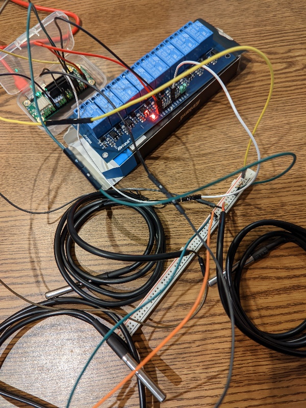
Here’s a preview of my desktop proof of concept:
More to come on my implementation with Home Assistant to provide smart thermostat access for a multi-zoned commercial building.
1 Like
Hi @RadxaYuntian, thank you for your help earlier this week!
As I’ve been implementing this thermostat config, I am wiring the DS18B20 temp sensors via parasitic power as the Zero only has access to two wires in the utility room from each sensor location.
I had previously suggested GPIOAO_3 as it indicates it is set to ‘pull up’ in:
/sys/kernel/debug/pinctrl/ff800000.sys-ctrl\:pinctrl@14-pinctrl-meson/pinconf-pins
After adding the meson-g12a-w1-gpioao-3-high overlay as you provided, this pin continues to show from the above file: (GPIOAO_3): input bias pull up, output drive strength (500 uA)
Do any other characteristics need to be set on the Zero for this kind of wiring config?
The manufacturer’s recommendations for parasitic power are here (esp. page 7 & figure 6):
https://raw.githubusercontent.com/May-DFRobot/DFRobot/master/DS18B20.pdf
For instance, does this pin need to be set as an open drain as well?
Does the Radxa Zero board provide resistance when set to pull up? Or is it expected to add an external resistor? I wasn’t sure where to measure this.
Measuring GPIOAO_3 shows Vout = 3.0V
Look forward to your thoughts, thank you in advance!
I think the device is able to (reliably) supply up to 4mA to GPIO. However you need to set it at pin controllor level. You can try if that can be changed within sysfs.
Due to Shenzhen (where our company is located) mandates work from home this week we can only provide reduced support on the forum at the moment. We hope to improve on this once things stabilize.
Hi @RadxaYuntian, thank you for the link and additional details especially from your home work environment.
I spent some time digging through the sysfs structure and reviewing potential pinctrl candidates, such as:
/sys/bus/platform/drivers/meson-g12a-pinctrl/ff634400.bus:pinctrl@40
/sys/bus/platform/drivers/meson-g12a-pinctrl/ff800000.sys-ctrl:pinctrl@14
Unfortunately I didn’t find anything specific to pin 7, GPIOAO-3 or 415. Likewise I didn’t find anything specific to drive-strength-microamp
How would sysfs be used to specify drive strength?
The sensor manufacturer lists up to 1.5mA draw, so I’m thinking to set this to 1.8mA to test (1800uA).
Is another way to set this in the overlay data blob?
Does specifying pull up on a Zero pin provide resistance? If so, how much?
I will need to account for this in selecting the impedance of the external resistor to ensure the available voltage is within range. I’ve been testing with the sensor manufacturer’s recommended 4.7k ohm resistor.
I appreciate your help and hope the situation in Shenzhen improves!
If there is no such thing defined in sysfs you might have to decompile the board dtb and add the property.
This post can show you how to do it.
To follow-up on this, while the pinctrl mechanism to update the drive strength was elusive, reviewing the existing pin output seemed to indicate GPIOC_7 is a good candidate, in fact out of all the GPIO pins, it seems to be the only one that’s set to pull up while at max output current:
grep GPIO /sys/kernel/debug/pinctrl/ff634400.bus:pinctrl@40-pinctrl-meson/pinconf-pins | grep 4000
pin 16 (GPIOH_0): input bias disabled, output drive strength (4000 uA)
pin 17 (GPIOH_1): input bias disabled, output drive strength (4000 uA)
pin 41 (GPIOC_0): input bias pull up, output drive strength (4000 uA)
pin 42 (GPIOC_1): input bias pull up, output drive strength (4000 uA)
pin 43 (GPIOC_2): input bias pull up, output drive strength (4000 uA)
pin 44 (GPIOC_3): input bias pull up, output drive strength (4000 uA)
pin 45 (GPIOC_4): input bias pull down, output drive strength (4000 uA)
pin 46 (GPIOC_5): input bias pull up, output drive strength (4000 uA)
pin 47 (GPIOC_6): input bias pull up, output drive strength (4000 uA)
pin 48 (GPIOC_7): input bias pull up, output drive strength (4000 uA)
pin 65 (GPIOX_0): input bias disabled, output drive strength (4000 uA)
pin 66 (GPIOX_1): input bias disabled, output drive strength (4000 uA)
pin 67 (GPIOX_2): input bias disabled, output drive strength (4000 uA)
pin 68 (GPIOX_3): input bias disabled, output drive strength (4000 uA)
pin 69 (GPIOX_4): input bias disabled, output drive strength (4000 uA)
pin 70 (GPIOX_5): input bias disabled, output drive strength (4000 uA)
Note: pin numbers are specific to each GPIO chip NOT the physical pin numbers. The device map does indicate the GPIO Names are accurate though.
When looking at the GPIO Wiki, GPIOC_7 is the only pin from this list that’s directly accessible. As it is an open drain, it requires Vcc or GND to be accessible. Could this mean connecting both Vcc via a pull up 4.7k ohm resistor and GPIOC_7 would allow parasitic power use?
After wrestling a build env into shape and doing my best to understand the reqs to turn device tree source (dts) into device tree blob objects (dtbo) with the device tree compiler (dtc), I made two new data objects (both source and blobs are enclosed):
meson-g12a-w1-gpioc-7-high_AND_low.zip (1.7 KB)
[zip file sha256sum: 7fecb43f902d21f446536e9c97b8339374613b6ae0949fd5234099bf2adaa7c2]
Testing both the high and low dtbo overlays with power + GPIOC_7 + 4.7k resistor + sensor signal wire on the same breadboard circuit did not expose the sensor via /sys/bus/w1/devices/
So it’s back to finding how to increase the drive-strength-microamp for GPIOAO-3.
Hi @RadxaYuntian, thank you for your response, I hope things are going as well as possible in Shenzhen and working from home!
Please confirm:
a) When ‘pull up’ is indicated for a pin, is any resistance applied from the Zero’s hardware?
b) Where would you expect to find access to modify drive strength via pinctrl in the /sys structure?
Much appreciated!
When you do external pull up the signal’s power is supplied by your external circuit, not SoC, so you don’t need to mess with drive strength.
Hi @RadxaYuntian, thank you again for your reply. There is no external circuit, only a DS18B20 temp sensor, which needs to connect to the Zero via parasitic power. This means it needs at least 3V and 1.5mA.
As GPIOC_7 doesn’t supply voltage, for GPIOAO_3 (or any other gpio pins at 3V or more)
Alternately, is there a way to include the drive strength parameter in the 1-wire overlay?