This article describes in three phases how to achieve an almost fan less SATA HAT with maintaining the lifetime of the equipment.
- Phase I „everybody could do“
- Phase II „read HDD temps“
- Phase III „bigger display“
Disclaimer:
The modifications in this article are based on my experiences and if you find them useful to use you do so at your own risk.
The major issue to solve was that the Pi even in idle generate a lot of heat and this raising up heat is additionally heating the on top of it mounted HDDs which are producing heat by themself.
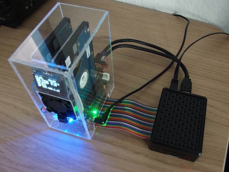
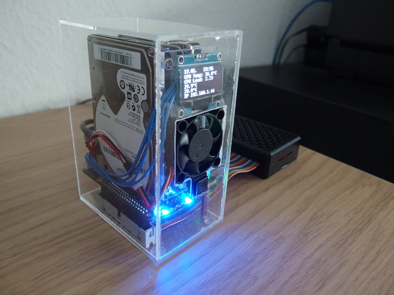
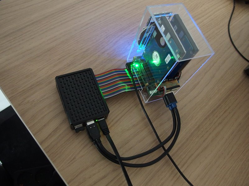
The solution to that is to separate HAT and Pi.
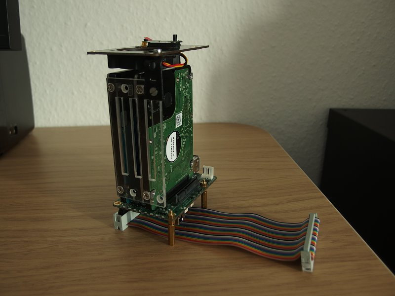
Phase I „everybody could do“
The first phase could be achieved by everybody as necessary parts could be bought and it requires no change on software, three items are needed:
- A aluminum case, the one used here keeps the Pi 4b fan less cooled in idle at 40 degree and on 100% load at 65 degree with room temperature around 20 degree
- A GPIO extension cable (15 cm)
- Two USB 3.0 A-Male to A-Female extension cables
The USB 3.0 connection adapter coming with the HAT has on both ends male connectors but is wired like an „extension“ cable (1:1).
Therefore a USB 3.0 A-Male to A-Male „connector“ cable can not be used as those have a swapped wiring.
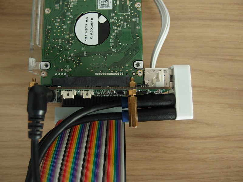
For the extension cables two things need to be considered:
- The thickness of the female connector should not exceed 9.2 mm
- The female connector surface should be plastic (not metal) to avoid unwanted electrical contact
Due to internal wiring of the connection adapter coming with the HAT the USB 3.0 cables need to be plugged in that way:
- top HAT connector to lower Pi connector
- lower HAT connector to top Pi connector
With that no software modification is required and the standard Top board can be used as indicated in the pictures.
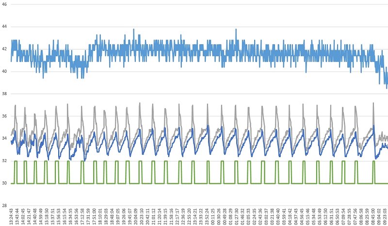
Phase II „read HDD temps“
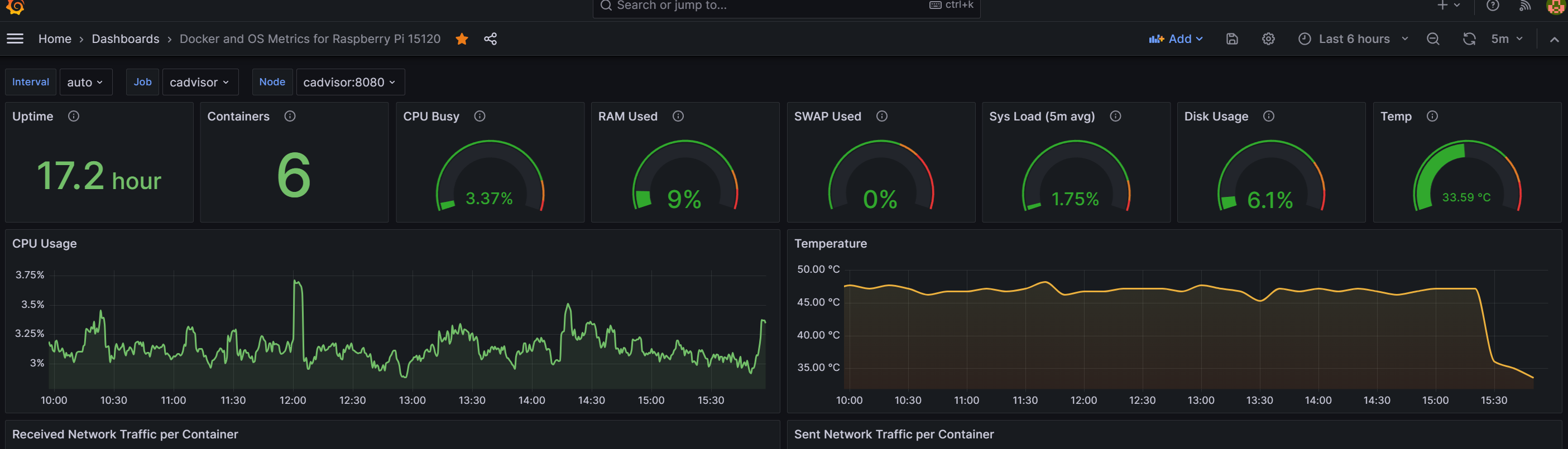
To ensure for all use cases a good temperature for the HDDs it is necessary to have some related measurements.
I did not find a way by available commands to measure the HDD temps when they are spun down to preserve lifetime without initiating a spin up caused by the measurement.
In that context „standby“ does not always seem to imply spun down.
The SATA HAT software already supports the reading of one w1 connected external temperature sensor. This external measurements are good indication to trigger fan if needed.
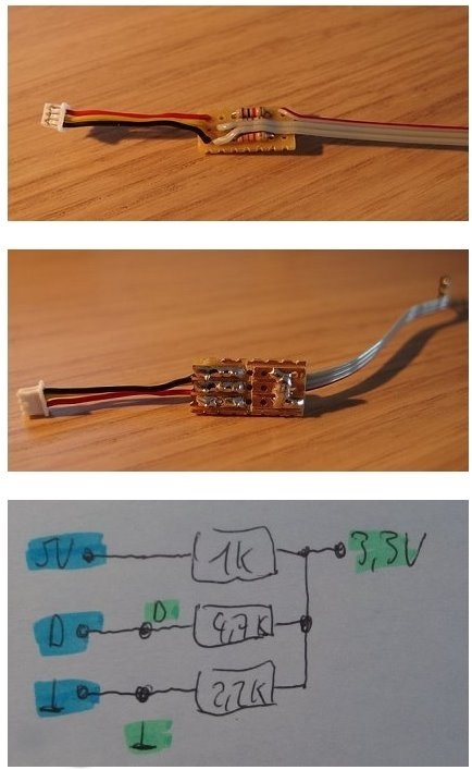
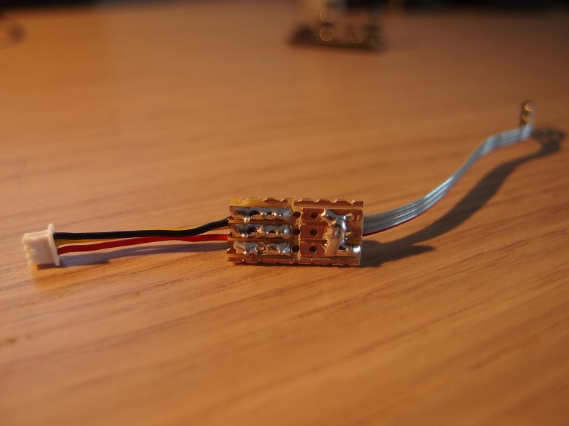
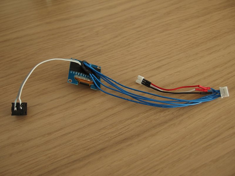
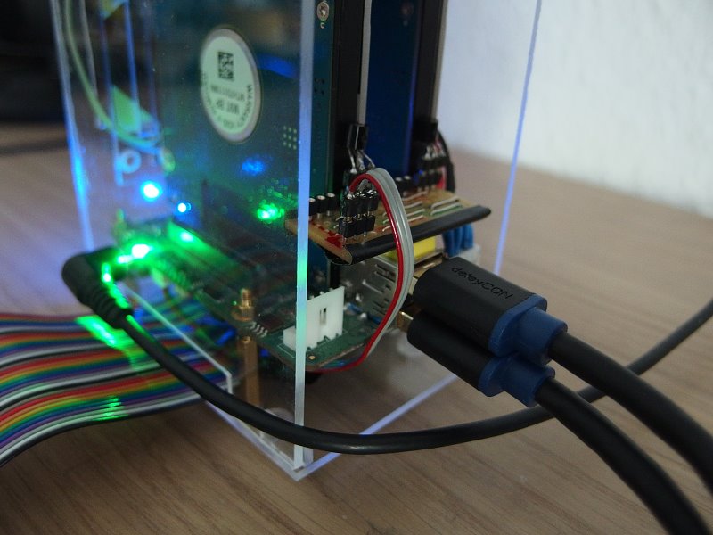
Starting from there putting things together with some not that difficult soldering work.
A board with up to 4 pluggable DS18B20 temperature sensors.
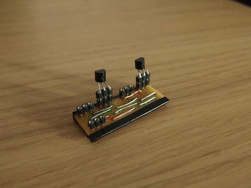
But how to connect sensors without e.g. soldering tapings on HAT GPIO?
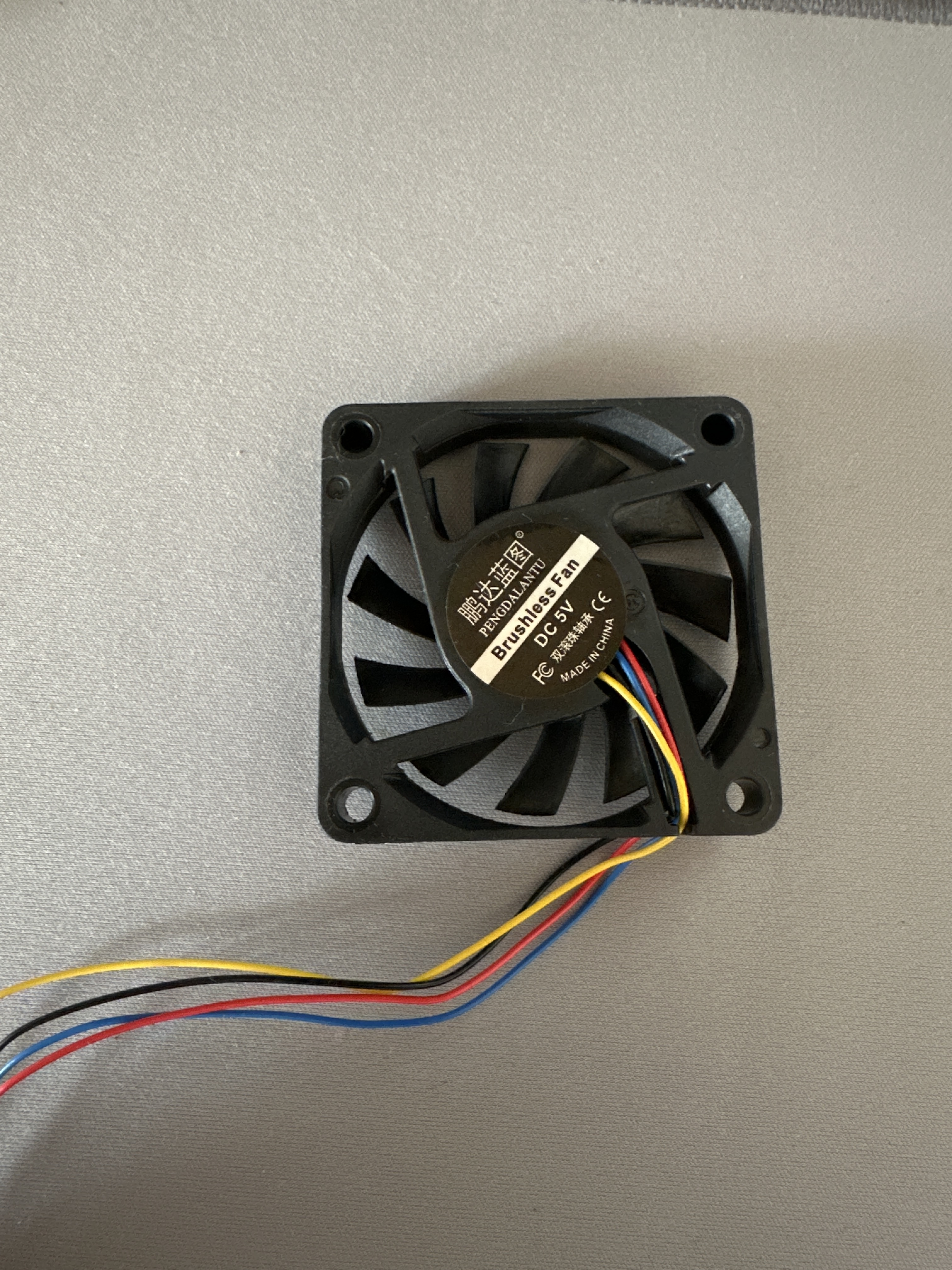
As the CPU fan socket of the HAT is not used anymore it is a perfect candidate for w1 usage.
The socket delivers a needed voltage supply, but at 5V.
This can be reduced by a 1k Ohm / 2,2k Ohm resistor divider to the needed 3,3V and should be accompanied with the 4,7k Ohm PullUp resistor for the data wire.
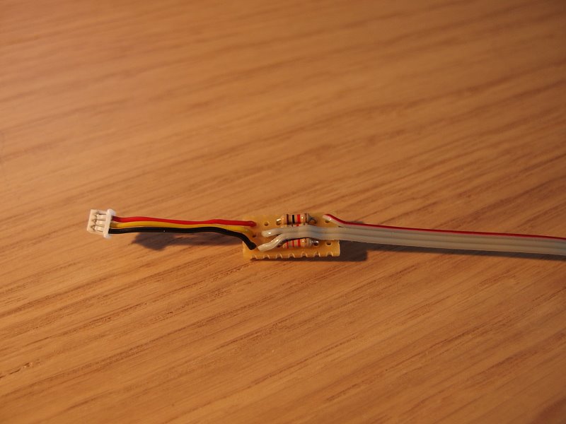
As GPIO 12 is now used for w1 instead of CPU fan a few changes in software are necessary and with that already one sensor can take his duties, e. g. if only the HAT case temperature is from interest to trigger fan.
In /boot/config.txt change or add
dtoverlay=w1-gpio,gpiopin=12
In misc.py extend
f.write(content.strip() + '\ndtoverlay=w1-gpio,gpiopin=12')
In fan.py change (as CPU is passively cooled)
#    return max(t1, t2)
     return t1
and comment out
# gpio.hardware_PWM(12, 0, 0)
and comment out
# gpio.hardware_PWM(12, 25000, dc * 10000)
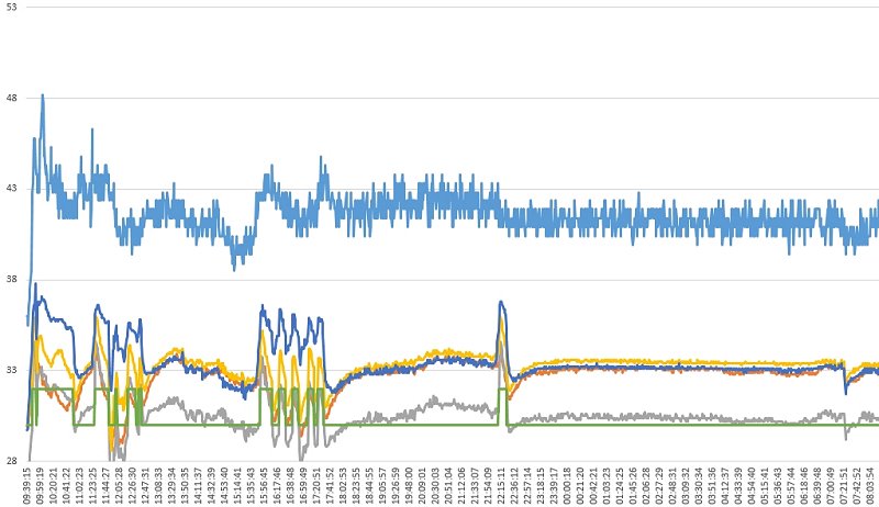
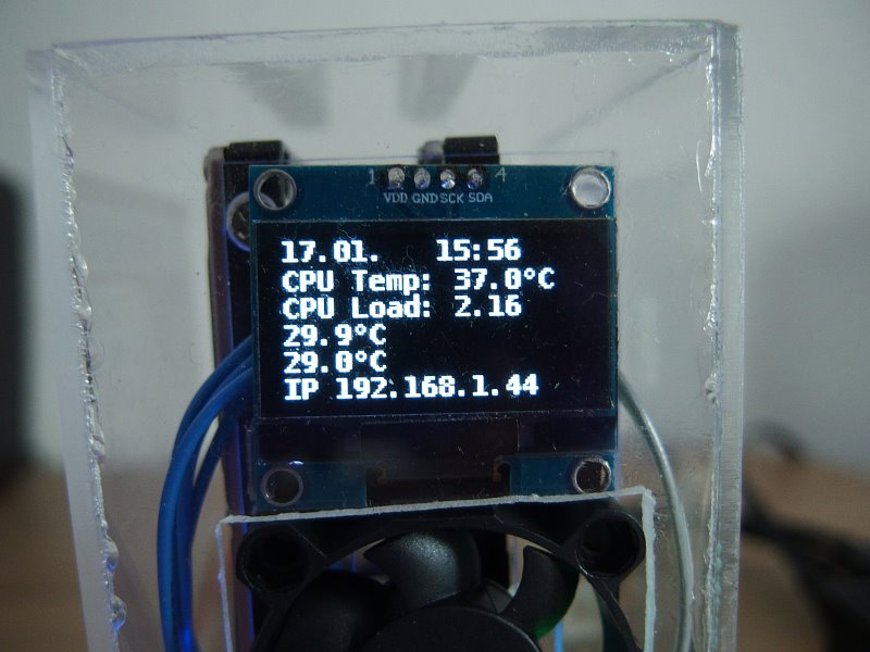
For displaying temperatures and using up to four sensors some more software changes are needed.
Below find the quick and „hard coded“ changes for two sensors.
In misc.py add
def get_w1_temp(i):
    temp = "{:.1f}°C".format(conf['w1'][i].value)
    return temp
and add after conf[‘oled’][‘f-temp’] = cfg.getboolean(‘oled’, ‘f-temp’)
        conf['w1'][0] = mp.Value('d', -1)
        conf['w1'][1] = mp.Value('d', -2)
        conf['w1'][2] = mp.Value('d', -3)
        conf['w1'][3] = mp.Value('d', -4)
In fan.py replace the whole read_temp and adapt the w1 IDs to yours
def read_temp(cache={}):
    w1_slave = cache.get('w1_slave')
    if not w1_slave:
        try:
            w1_slave = next(Path('/sys/bus/w1/devices/').glob('28*/w1_slave'))
        except Exception:
            w1_slave = 'not exist'
        cache['w1_slave'] = w1_slave

    if w1_slave == 'not exist':
        t1 = 42
        t2 = 42
    else:
      try:
        w1_slave = '/sys/bus/w1/devices/28-3c01b5561f5f/w1_slave'
        with open(w1_slave) as f:
            t1 = int(pattern.search(f.read()).groups()[0]) / 1000.0
            misc.conf['w1'][0].value = t1
      except Exception as e:
        logging.info("show EX 1: "+str(e))
        t1 = 42

      try:
        w1_slave = '/sys/bus/w1/devices/28-3c01b5564d06/w1_slave'
        with open(w1_slave) as f:
            t2 = int(pattern.search(f.read()).groups()[0]) / 1000.0
            misc.conf['w1'][1].value = t2
      except Exception as e:
        logging.info("show EX 2: "+str(e))
        t2 = 42

    with open('/sys/class/thermal/thermal_zone0/temp') as f:
        tC = int(f.read().strip()) / 1000.0

    return max(t1, t2)
As already said it is quick code and can be made with loops and configuration more comfortable.
In oled.py e.g. replace displaying IP by temperatures
#            {'xy': (0, 21), 'text': misc.get_info('ip'), 'fill': 255, 'font': font['11']},
            {'xy': (0, 21), 'text': misc.get_w1_temp(0), 'fill': 255, 'font': font['11']},
            {'xy': (64, 21), 'text': misc.get_w1_temp(1), 'fill': 255, 'font': font['11']},
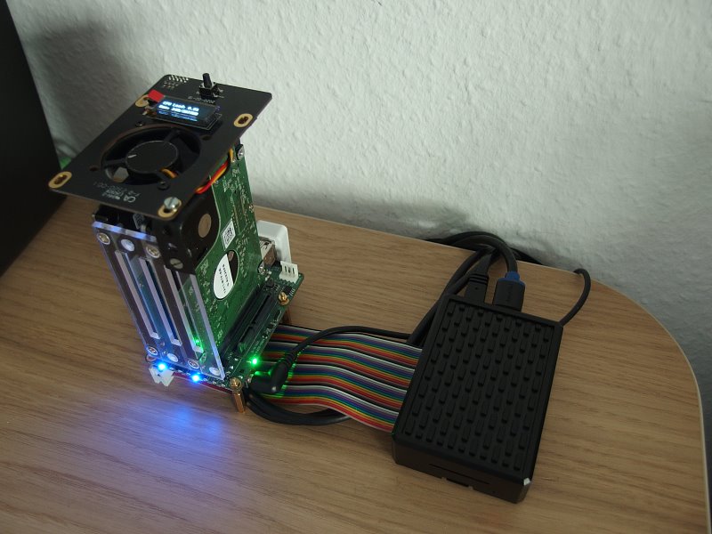
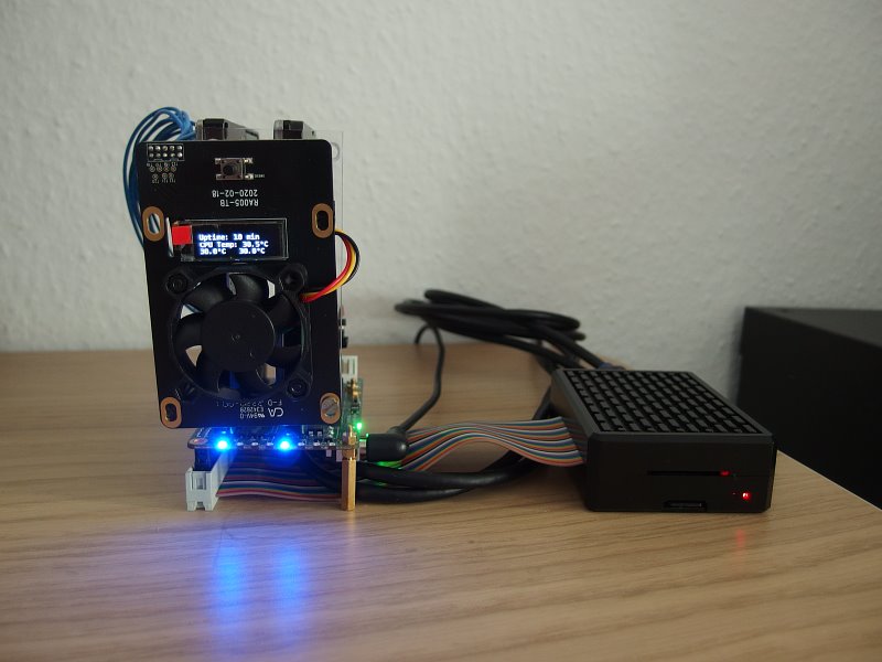
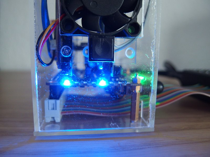
My preferred solution is a front mount of the Top board with the fan blowing.
For that a slight longer HAT to Top board cable is needed (JST PHD 2x5).
Phase III „bigger display“
For my personal needs I liked to have
- shorter and A-male to A-male USB 3.0 cables
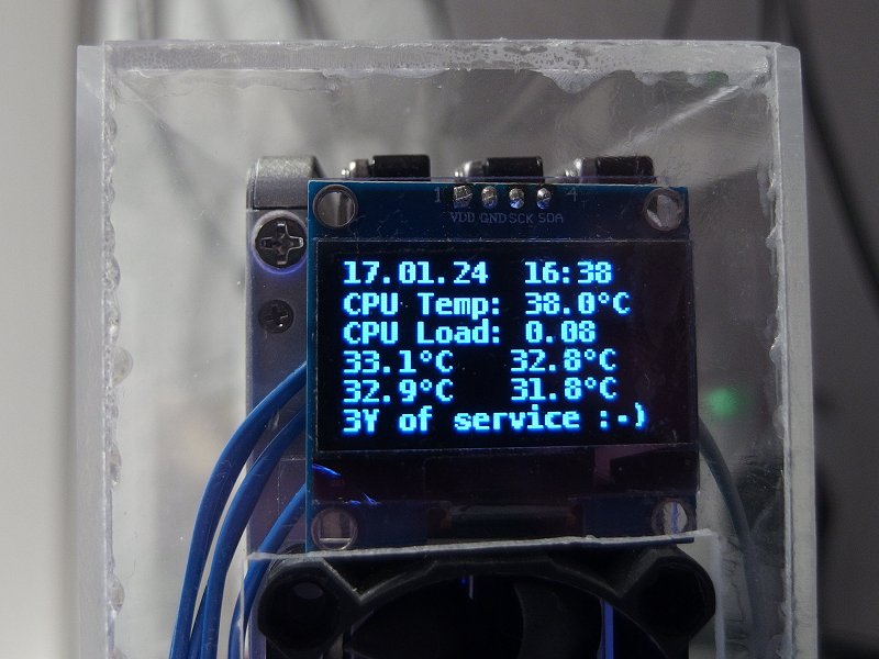
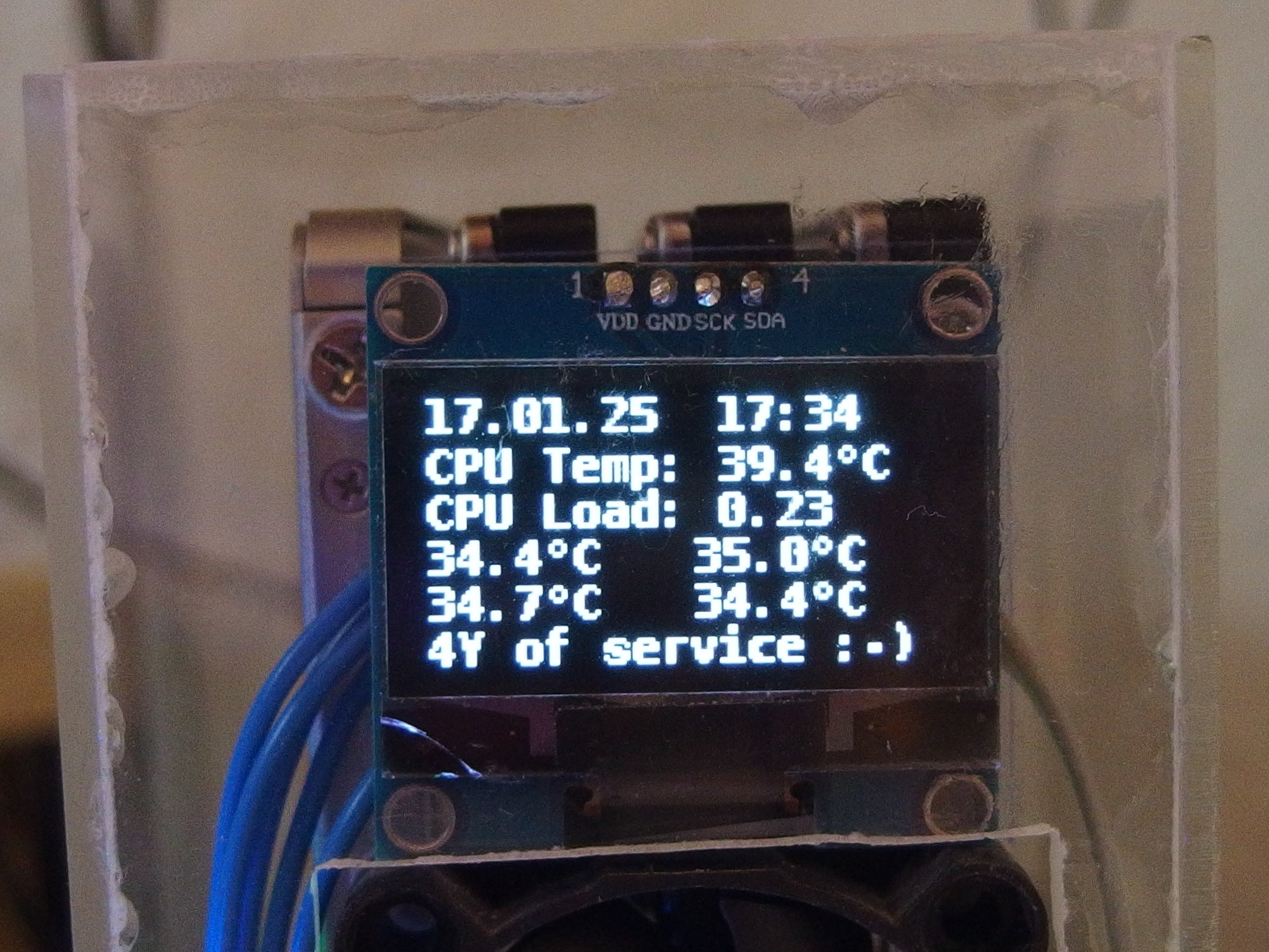
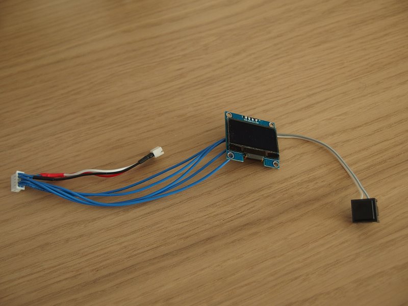
- a bigger display to have information needed on one page
- to by key toggle display on/off to preserve its lifetime
As described above the A-male to A-male need to be wired as kind of „extension“, means 1:1 without swapping wires.
I bought a standard A-male to A-male cable, cut it in two halves, identified the half with the swapped wires and considered this to „unswap“ when soldering the connector on the cut end.
I found a SH1106 controlled 128x64 OLED. To install execute
sudo -H pip3 install luma.oled
Now the software changes for the SH1106 display and the new action of the key to toggle the display on/off.
In main.py change
    #    'slider': lambda: oled.slider(lock),
    'slider': lambda: oled.slider_key(lock),
In misc.py extend
conf = { 'disk': [], 'idx': mp.Value('d', -1), 'run': mp.Value('d', 1), 'hidden': mp.Value('d', 0) }
And finally replace oled.py with this (which is pretty close to the original oled.py)
#!/usr/bin/python3
import time
import misc
from PIL import Image
from PIL import ImageDraw
from PIL import ImageFont

from luma.core.interface.serial import i2c
from luma.oled.device import sh1106

font = {
    '10': ImageFont.truetype('fonts/DejaVuSansMono-Bold.ttf', 10),
    '11': ImageFont.truetype('fonts/DejaVuSansMono-Bold.ttf', 11),
    '12': ImageFont.truetype('fonts/DejaVuSansMono-Bold.ttf', 12),
    '14': ImageFont.truetype('fonts/DejaVuSansMono-Bold.ttf', 14),
}

device = None

def disp_init():
  global device
  serial = i2c(port=1, address=0x3C)
  device = sh1106(serial)
  return None

try:
    disp = disp_init()
except Exception:
    misc.open_w1_i2c()
    time.sleep(0.2)
    disp = disp_init()

image = Image.new('1', (128, 64))
draw = ImageDraw.Draw(image)

def disp_show():
    im = image.rotate(180) if misc.conf['oled']['rotate'] else image
    try:
      device.display(im)
    except Exception as e:
      pass
    draw.rectangle((0, 0, 128, 64), outline=0, fill=0)

def welcome():
    draw.text((0, 0), 'ROCK Pi SATA HAT', font=font['14'], fill=255)
    draw.text((32, 16), 'loading...', font=font['12'], fill=255)
    disp_show()

def goodbye():
    draw.text((32, 8), 'Good Bye ~', font=font['14'], fill=255)
    disp_show()
    time.sleep(2)
    disp_show()  # clear

def gen_pages():
    pages = {
        0: [
            {'xy': (0, -3), 'text': time.strftime ('%d.%m.   %H:%M'), 'fill': 255, 'font': font['11']},
            {'xy': (0, 9), 'text': misc.get_cpu_temp(), 'fill': 255, 'font': font['11']},
            {'xy': (0, 20), 'text': misc.get_info('cpu'), 'fill': 255, 'font': font['11']},
            {'xy': (0, 31), 'text': misc.get_w1_temp(0), 'fill': 255, 'font': font['11']},
            {'xy': (0, 42), 'text': misc.get_w1_temp(1), 'fill': 255, 'font': font['11']},
            {'xy': (0, 53), 'text': misc.get_info('ip'), 'fill': 255, 'font': font['11']},
        ]
    }
    return pages

def slider_key(lock):
    misc.conf['hidden'].value = not(misc.conf['hidden'].value)
    slider(lock)
    global device
    if not(misc.conf['hidden'].value):
      device.show()
    else:
      device.hide()

def slider(lock):
    with lock:
      if not(misc.conf['hidden'].value):
        for item in misc.slider_next(gen_pages()):
           draw.text(**item)
        disp_show()

def auto_slider(lock):
    while misc.conf['slider']['auto']:
        slider(lock)
        misc.slider_sleep()
    else:
        slider(lock)
`
Hope you enjoyed reading and find it inspiring – have fun 
Michael
Everything you do - you do so at your own risk