Alright, I got a bit obsessed with this project.
First, I discovered that my stress-testing method is suboptimal. The sysbench command that I was using was only pegging one of the four cores to 100%.
Here’s the new command I’m using to stress test, which pegs all four cores to 100%:
sudo apt-get install stress
stress --cpu 4
Otherwise, I kept the same test procedure as before:
- Start a stress test
- Wait at least 20 minutes
- Measure for at least 20 minutes
- Average the measurements
I decided that measuring hard drive temperatures for these tests is irrelevant.
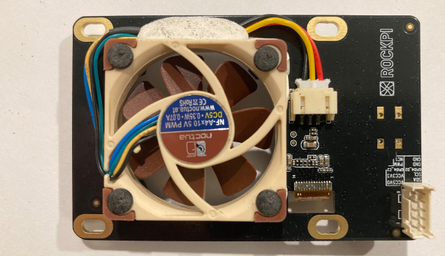
I decided to use the following mods as a baseline for further experiments:
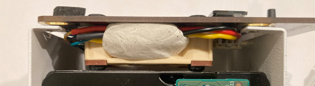
- Use sticky tack to make a gasket at the top
- Cover the side holes with tape
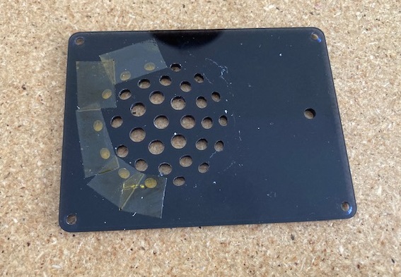
Additionally, I covered the following holes in the top hat with tape on the inside, since they allowed air to flow outside the gasket:
I ran a multi-core stress test against this baseline setup. The difference is dramatic:
- Single-core: 47.59 °C
- Multi-core: 56.85 °C
That’s a huge difference! Remember that the test I did earlier for an unmodded case showed 59.39 °C when stressing a single core. I think it’s reasonable to assume that we’d see temperatures above 60 °C if we were to stress-test all four cores. However, I don’t feel like undoing all of the mods I’ve done (which I’ll get into momentarily) just to see how big of a temperature improvement they’ve made.
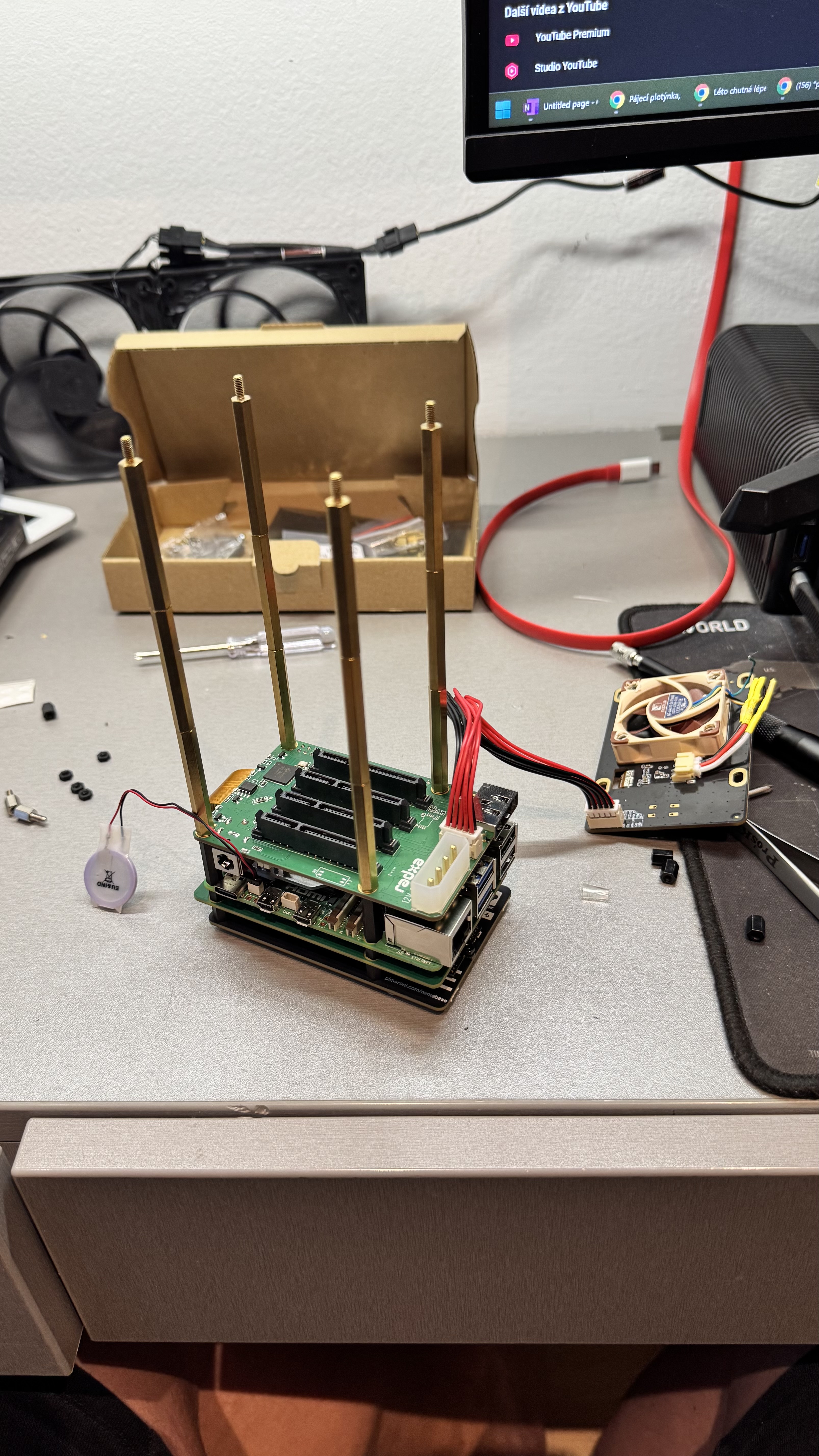
With the baseline recorded, I made some big changes.
First, I made some changes to my /boot/config.txt:
# Reduce idle frequency, avg. 400 (default 600, avg. 700)
arm_freq_min=200

# Enables dynamic voltage
# https://www.raspberrypi.org/forums/viewtopic.php?f=29&t=257394
dvfs=1

# Undervolt to reduce temps, can only go one step
# This results in 0.8350V (default 0.8600V)
over_voltage=-1
I don’t think the dvfs directive actually does anything in this instance. Reducing arm_freq_min should lower idle temperatures a little. I ran a stress test after undervolting, and got 55.47 °C for a gain of 1.38 °C. Not much to write home above, but I’m keeping it, so that’s our new baseline.
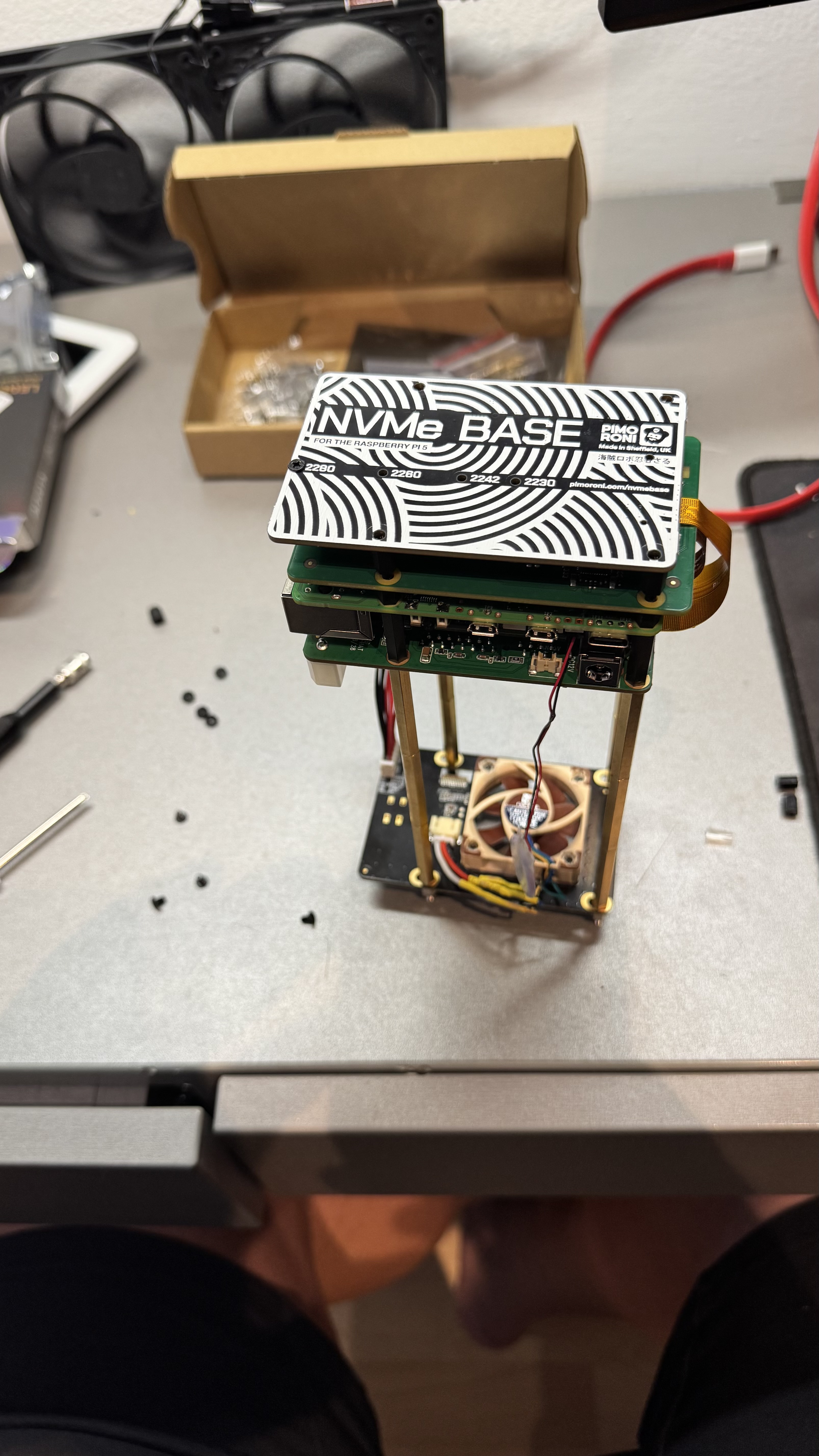
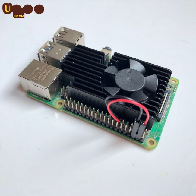
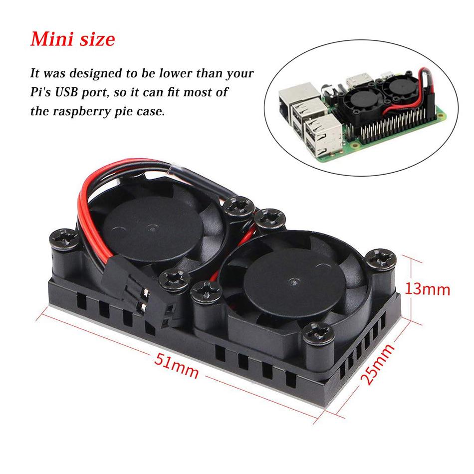
Next, I got a new heatsink:
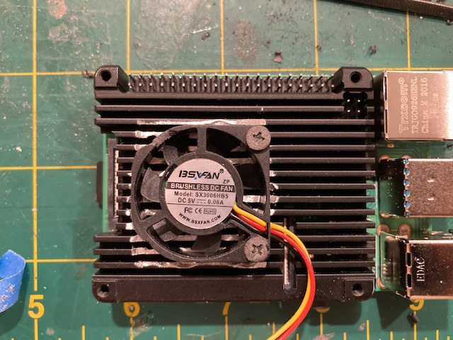
I bought the Geekworm Raspberry Pi 4 11mm Embedded Heatsink (P165-B). I bought both the P165-A and the P165-B. The P165-A is a piece of crap. There are some reviews which say that the heatsink don’t contact the components correctly. I can say from trying both heatsinks that those reviews are referring to the P165-A. The P165-B is almost perfect, however. You must use thermal paste, not thermal pads. Otherwise, it fits my RPi 4B perfectly.
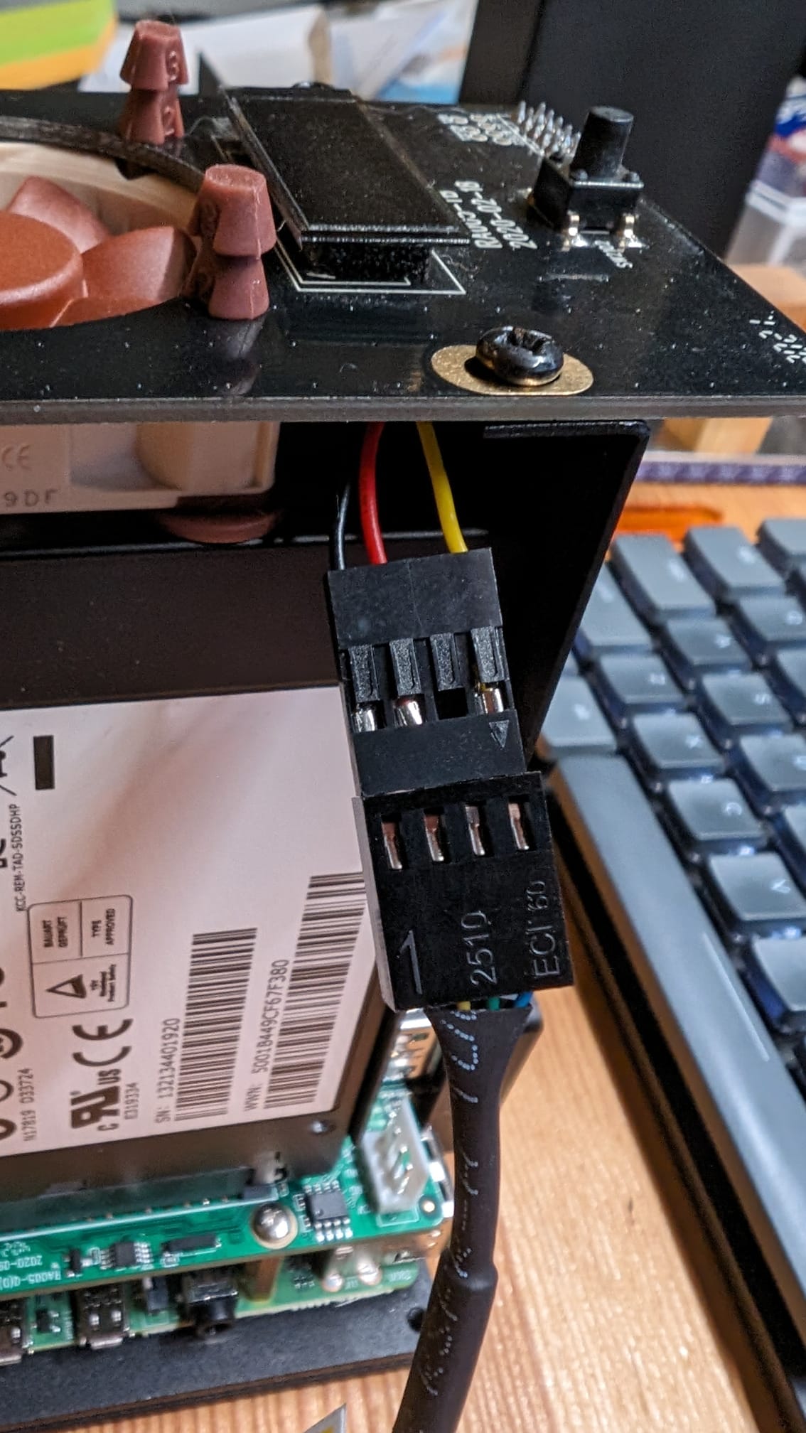
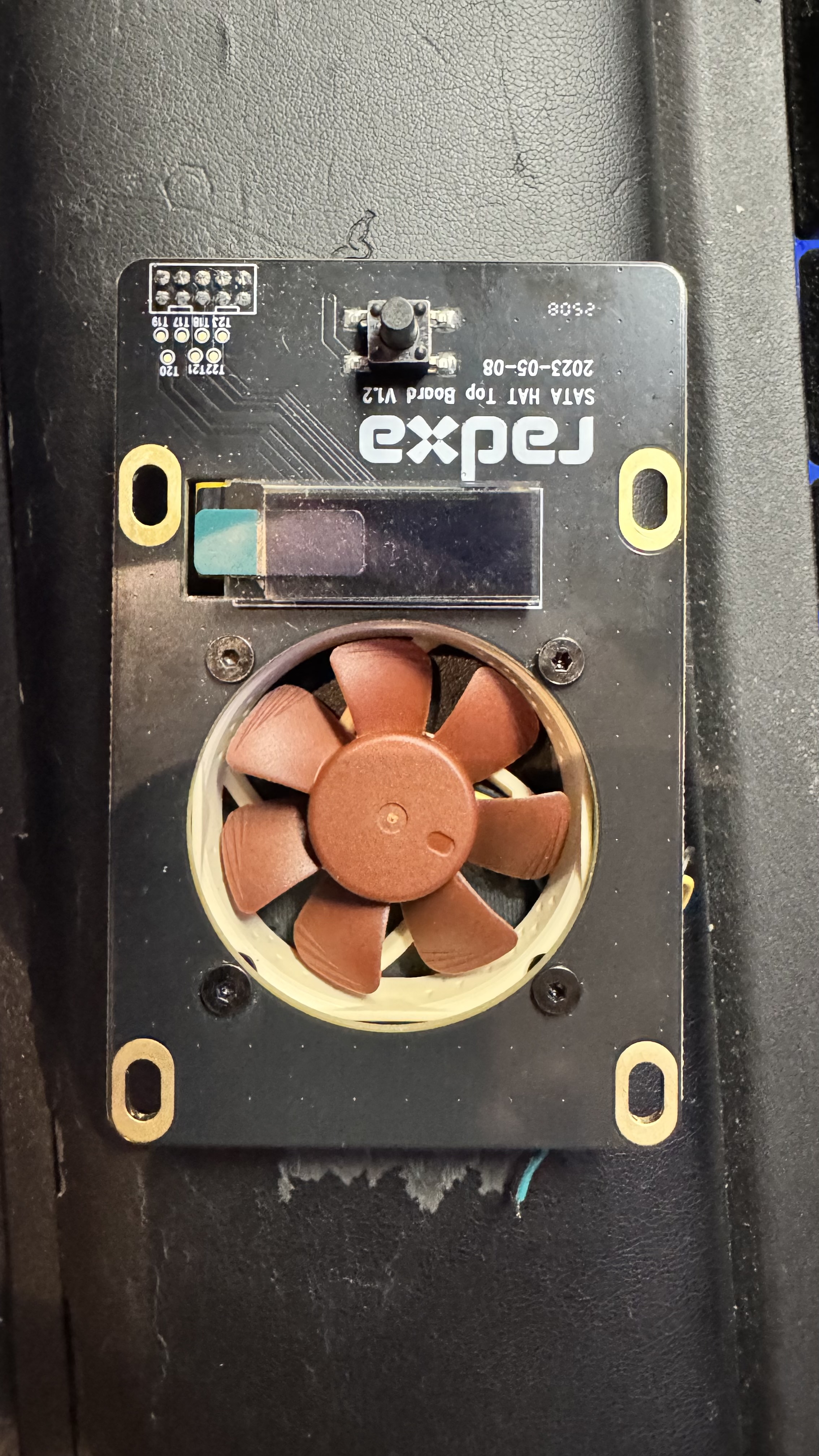
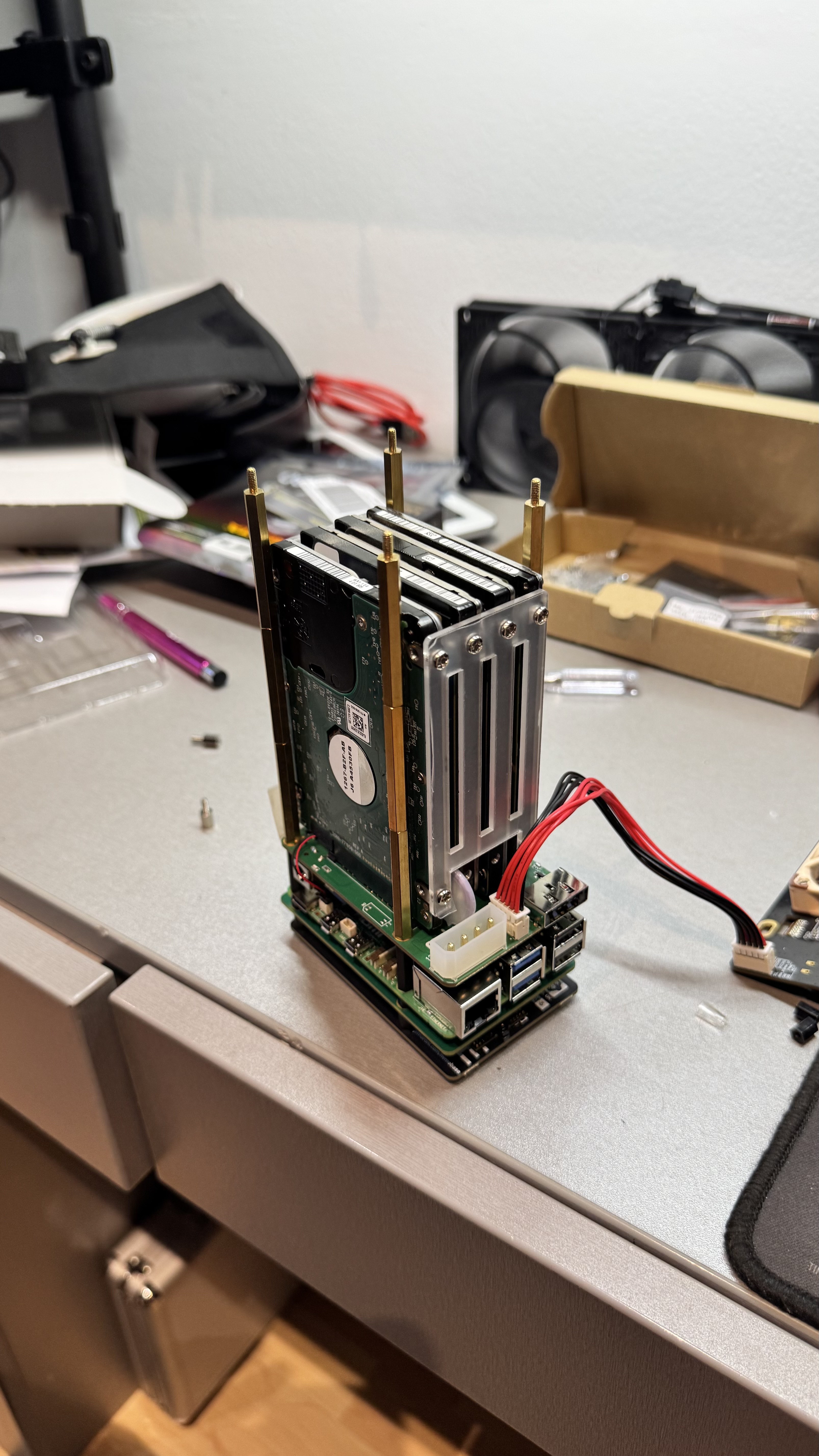
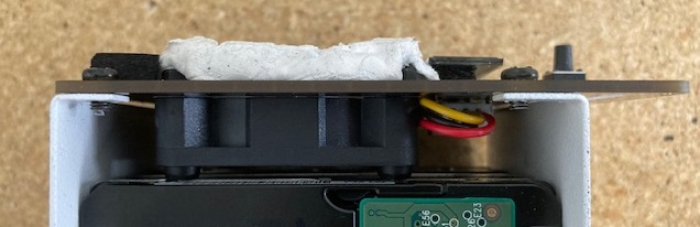
I decided to reuse the fan that came with the SATA case. I had to file down some of the plastic casing on the fan so that it wouldn’t collide with the power jack and the 1R5 inductor (?) on the SATA HAT. You can see the notch I filed for the inductor in the photo below.
Additionally, in order to get the fan to fit into the heatsink, I had to remove about 1.3-1.5mm of aluminum from where the fan sat on the heatsink. This was a big pain. I used a drill press with a 1/4" bit to carefully remove some material from the heatsink, and then, some files to finish the job. I would absolutely not recommend doing that. A rotary tool would have worked better, but I didn’t have one on hand, and I wanted it done ASAP.
This heatsink is tapped for M3 screws, but the screws provided with the default heatsink for the SATA HAT are M2.5. I had some nylon M3 screws on hand, so I sanded their heads down, so that they wouldn’t collide with the component leads sticking out of the SATA HAT PCB.
With the new heatsink, my quad-core stress test resulted in 49.29 °C for a gain of 6.18 °C versus the undervolted baseline of 55.47 °C.
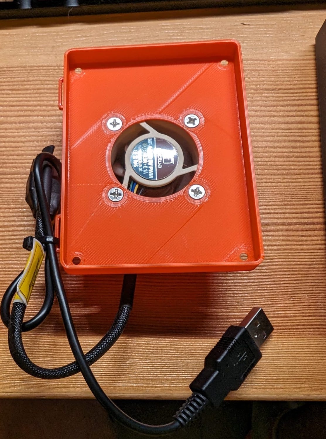
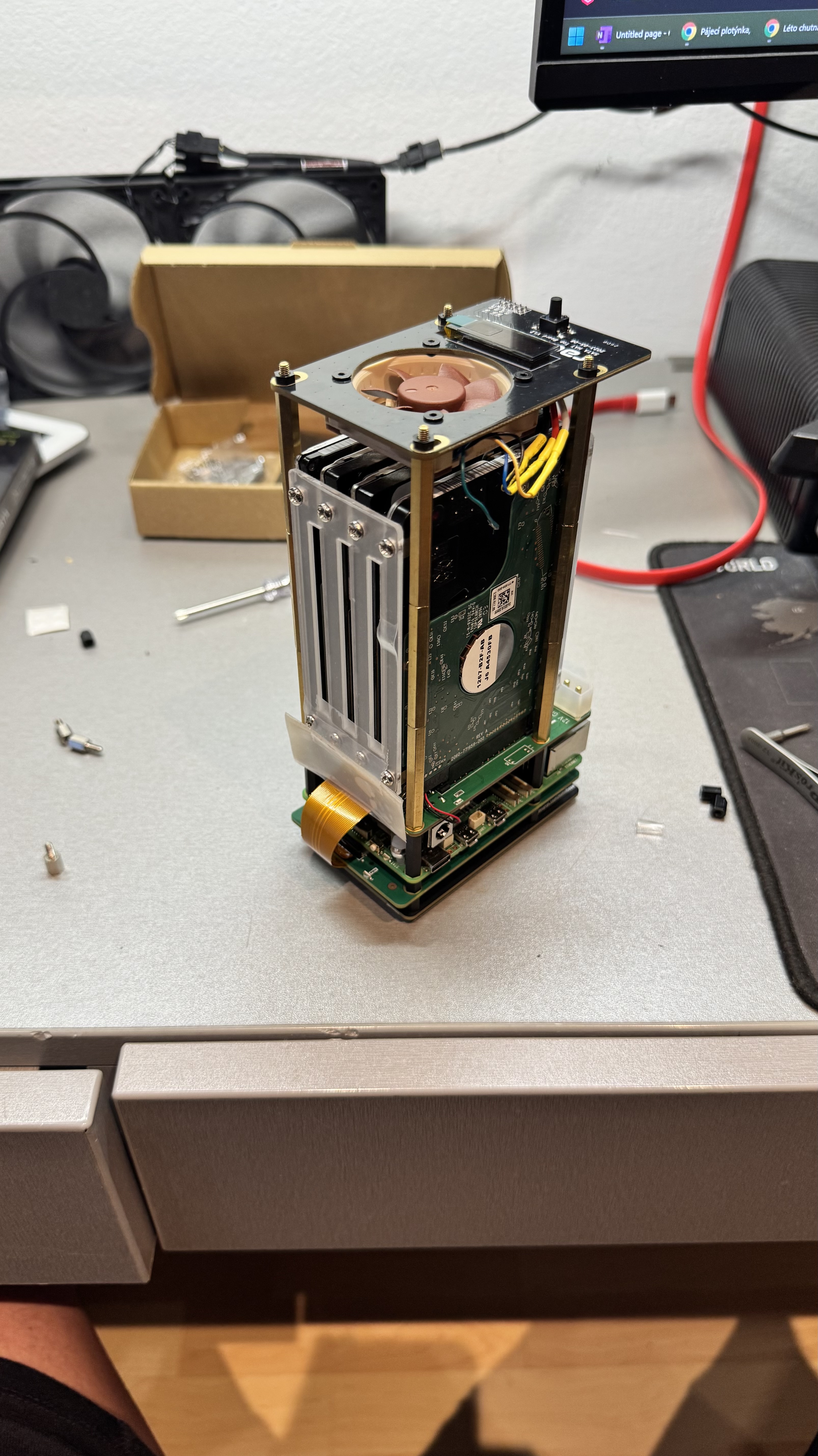
I decided to take it one step further and reverse the fans. This fan now blows air onto the CPU:
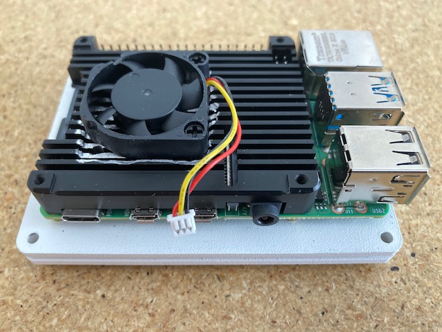
I had to make a new notch for the 1R5 component, and I had to make some new screws for this setup. The heads on the M3 screws were too wide. I stuck a standoff into a drill, screwed a 20 mm nylon screw into it, and held some 100 grit sandpaper to the screw while letting the drill do its thing. I used some side-cutters to shorten the screws to about 9.5-10mm.
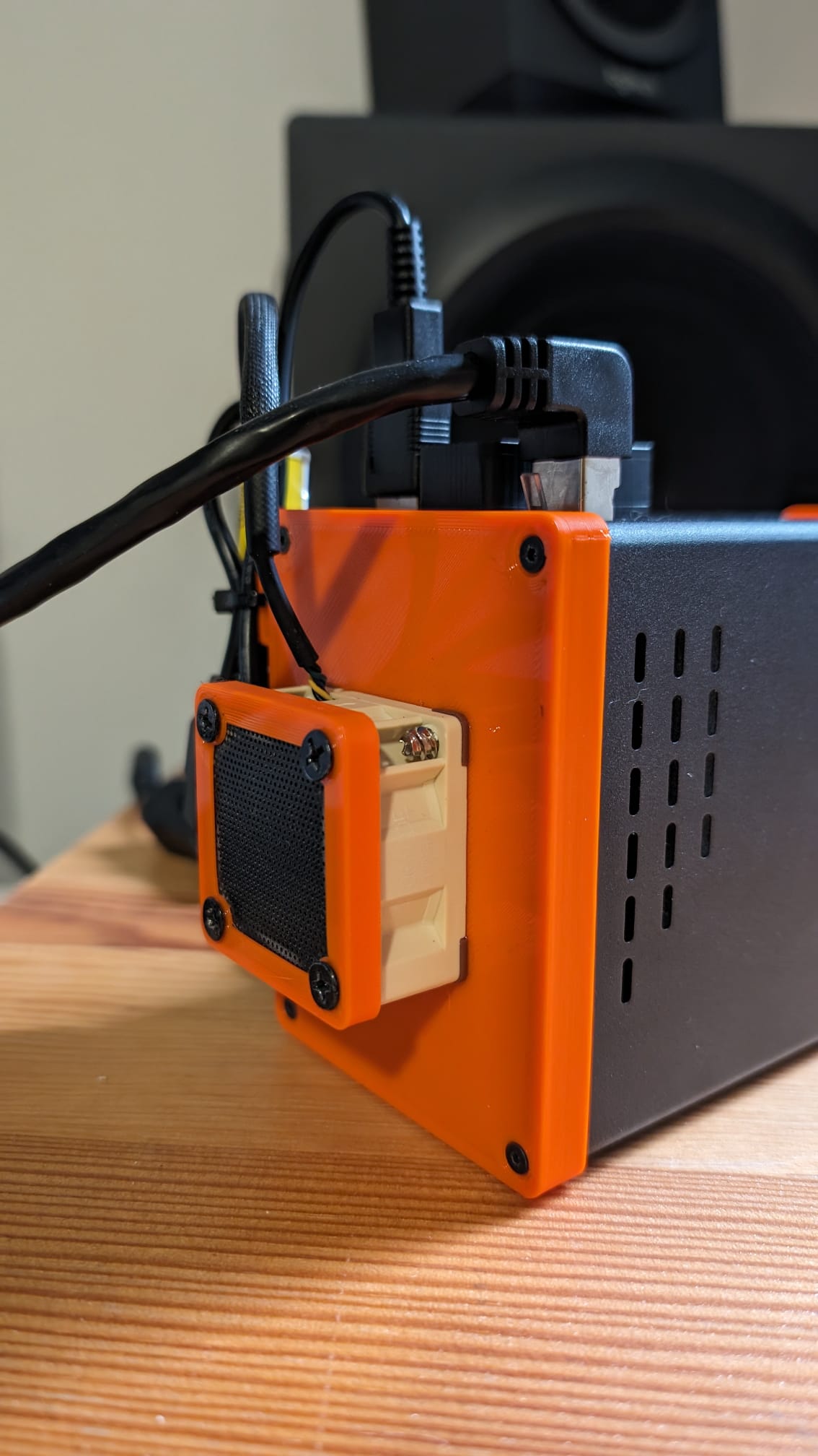
Lastly, I removed the tape that was covering the holes on the side, and I flipped the fan on the top hat around so that it sucked air into the case, instead of blowing it out:
I used some 20 mm nylon M3 screws here, too, and snipped them to the correct length. Tentatively, having the top fan in this orientation makes it less noisy, even at the same speed. Sucking the air through the holes makes less noise than blowing air through them?
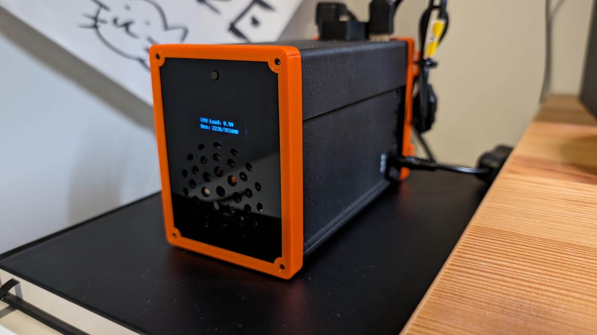
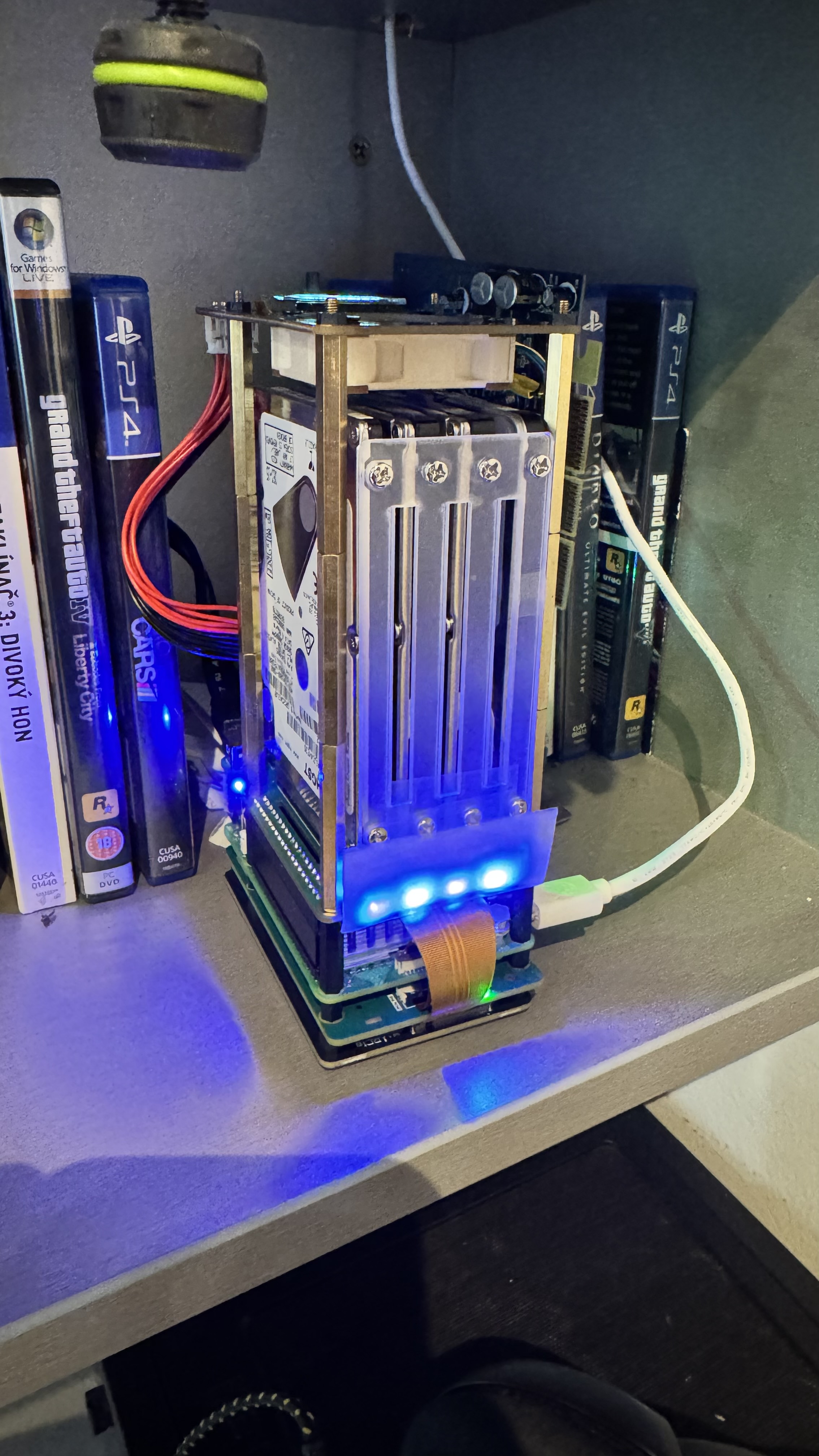
With that done, my final results are as follows:
- Quad-core stress test: 48.02 °C
- Idle: 44.52 °C
I ran that stress test for 2.7 hours, and in that time, it peaked above 50 °C for only one second!
Unfortunately, my idle temps do peak above 45 °C periodically, every few minutes or so.
I’m going to tinker with the top fan speed so that it doesn’t jump from 50% at 40 °C to 75% at 45 °C. Maybe having a smoother transition instead of a sharp jump, or even just having it run at like 55-60% at 40 °C will keep the temps from hitting 45 °C.
I’m also going to put the hard drives to sleep after a period of inactivity, using hdparm:
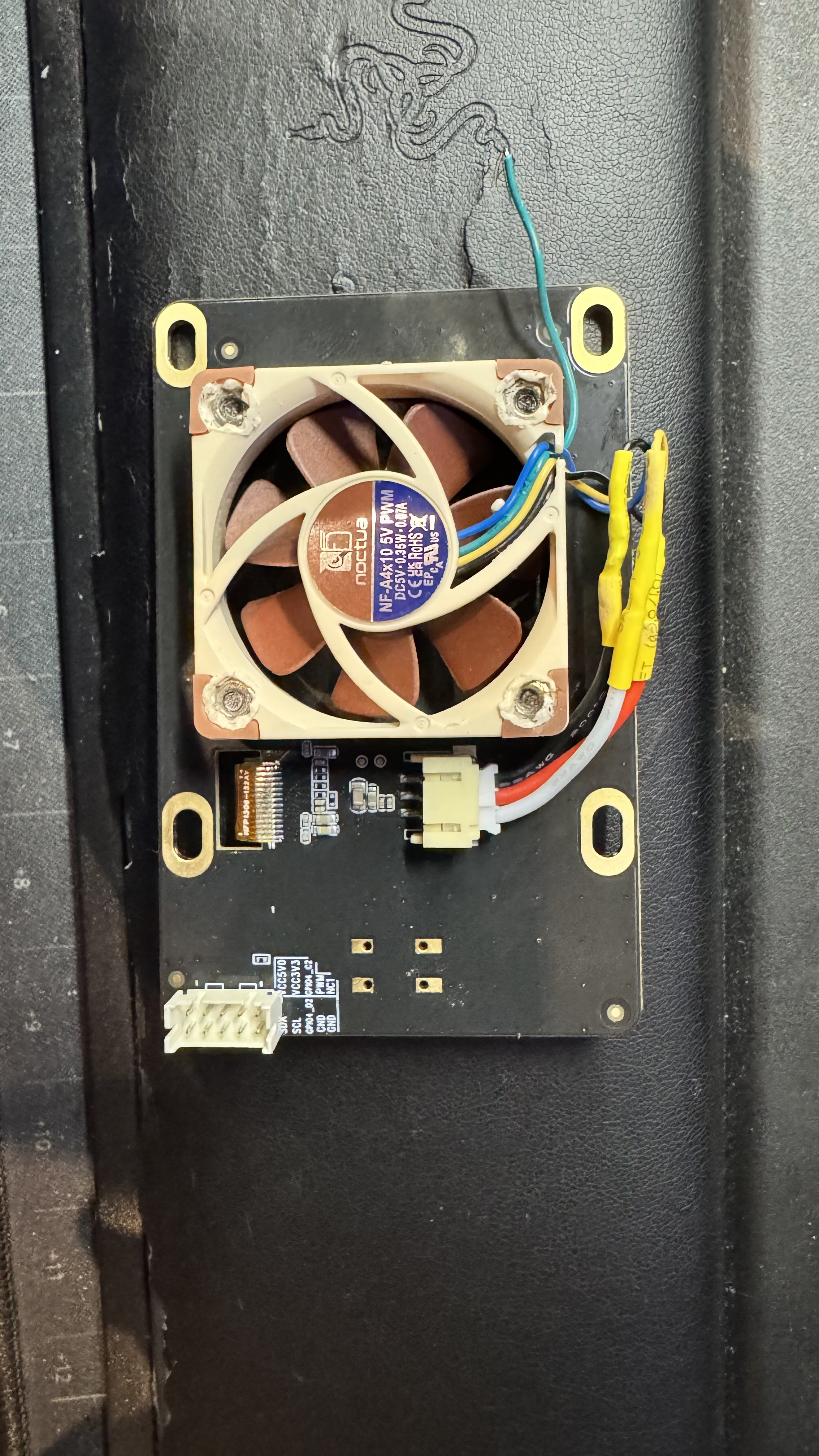
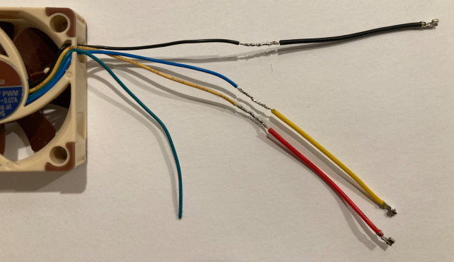
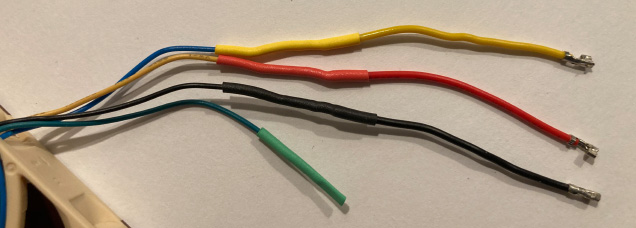
Lastly, I did order the 4-pin PWM 5V NF-A4x10 Noctua fan for the top hat. It should be coming in this week. Will be interesting to see how it affects temps.
I recognize this is probably obsessive at this point, but it’s been a lot of fun figuring out how to optimize this thing. I ordered this product knowing that I was going to tinker and hack with it, and it has definitely delivered in that regard so far.
 . Very entertaining to read though and I’m curious what the noctua fan will bring. I might still post some benchmark of my final result since I’m also tinkering around to get the coolest SATA hat. And maybe the race for the coolest sata hat is not over yet ^^
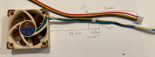
 )
)