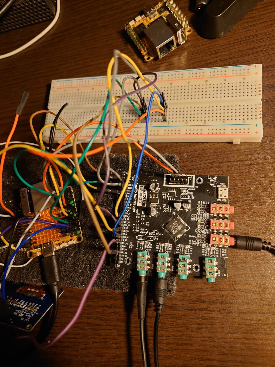
Hope it can be useful for the community so I’m sharing it here. Was able to connect cheap CS42448 DAC with RockPI S. DAC can be found on Aliexpress for about 28-30€.
CS42448 is a multichannel DAC/ADC, provides 8Ch outputs and 6Ch inputs and up to 192Khz/24-Bit.
It has a requirement for MCLK since there’s no crystall on-board so it works as a slave fully driven by RockPi S in I2S_TDM mode.
I’ve created DT overlay and small kernel patch for this DAC to work correctly. The Kernel patch required to increase PL330 DMA buffer and maxburst size in rockhip_i2s_tdm driver for the DAC to work in 8 channels mode at higher sample and bit rates. TDM_SHIFT_CTRL also needs to be changed to avoid sound distortion.
I’m using native Radxa kernel stable-4.4-rockpis branch, so no idea if it works with latest kernel versions.
Repo with info and patches
cs4248.dts
0001-Increase-DMA-buffer-size-and-maxburst-to-handle-high.patch
1 Like
Hi, thanks a lot for your info.
Actually I have been trying to run I2S0 at 96kHz cleanly, no result. Please see Rock Pi S - I2S0 - anyone getting clean 96/192kHz?
I tried the dma burst = 16 in the i2s driver earlier, no improvement. Your PL330 DMA change is very interesting, thanks a lot for the hint. I changed the MCODE_BUFF_PER_REQ to 1024 and NR_DEFAULT_DESC to 256, quite generous. The result got probably a bit better, but I still get several corrupted sample per minute on the I2S0 8ch loopback (just lines SDOx connected to SDIx) at 96kHz, and many issues at 192kHz. As my thread says, I am raising DMA clock significantly too, no clean result.
I am running kernel 6.6., patched with https://lore.kernel.org/all/[email protected]/ I wonder what could be screwed up in the process of mainlining the driver.
Please would you by any chance be willing to check your I2S0 loopback for stable bit perfection?
To minimize local CPU impact I use a locally-stored wav truncated at sine boundary, so that it can be concatenated:
sox -V  -r 96000 -c 1 -n -b 32 -c 8 8ch-96-sine.raw synth 240000s sine  4k gain -3

(while true; do cat 8ch-96-sine.raw; done ) | aplay -v -r 96000 -c 8 -f S32_LE -t raw -D hw:GenericStereoAu
Capturing spectrogram 120 secs long in another terminal:
sox -V -r 96000 -c 8 -b 32 -t alsa hw:GenericStereoAu,1 -n spectrogram -z 180 -w kaiser -d 120
Viewing the generated spectrogram.png after scp transfer on my PC.
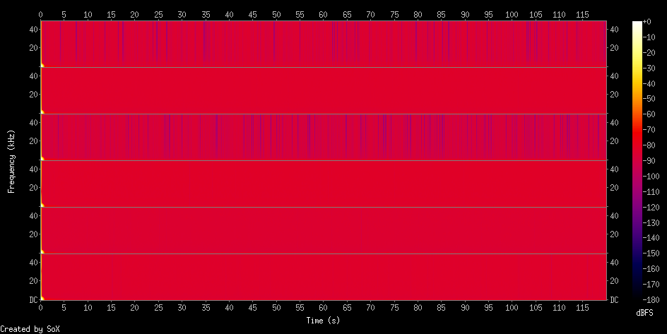
Hi, that’s what I got on the spectrogram:
Thanks a lot for your fast response. Your spectrogram suggests some issue in your test chain. Do you have same format for I2S OUT and IN? It should be similar to the spectrograms in my thread, just ideally no vertical lines - the glitches, only the horizontal lines at 4kHz. Any single incorrect sample produces a clearly visible vertical line.
It’s useful to capture the signal to wav and view the time waveform e.g. in audacity on a PC.
The single dropped/zero samples I experience produce a faint but clearly audible click in the sine signal. But I believe your project does not have the issue at the level of your spectrogram as such sample corruption would be very audible.
Literally I copy-pasted your commands above, except changing hw device string. In my case I’ve 8OUT/6IN and no separate subdevice for ADC, ie:
# aplay -l
card 0: Loopback [Loopback], device 0: Loopback PCM [Loopback PCM]
...
card 1: cirruscs42448 [cirrus,cs42448], device 0: ff300000.i2s-cs42448 cs42448-0 [ff300000.i2s-cs42448 cs42448-0]
  Subdevices: 1/1
  Subdevice #0: subdevice #0
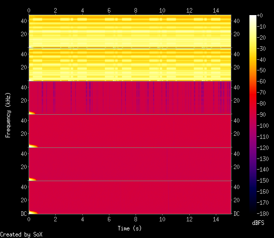
1OUT:1IN loopback spectrogram using audio cable, sadly I can’t connect remaining ones - have no more spare cables 
Audio cable means DAC -> ADC or connecting SDO0 SDI0 with a coax cable? Just a very short wire to connect the two header pins would do.
The spectrogram shows some sign of the signal at the beginning - does the while true loop work correctly in your shell? You can pipe the while true loop output to sox directly to check the generated signal (something like | sox -V -r 96000 -b 32 -c 8 -f raw -e signed-integer - -n spectrogram…)
How do you have the tx/rx clock sync on your I2S0?
I have 3.5 jacks soldered onboard for each IN/OUT. 4 OUT/3 IN jacks in total. One of the DAC outputs connected to the headphones, another DAC output connected to the the ADC input. I can hear high pitch sound during test from the headphones, it’s constant and clear without distortions of any kind. Signal in the beginning is a short “pop/click” produced by the system when I start recording.
How do you have the tx/rx clock sync on your I2S0?
I ended up using rockchip,clk-trcm = <1> in my DT (1: only tx_lrck/bclk is used) so I assume only TX used for clocking.
PS: for the output I’m using I2S TDM mode
So you have I2S TDM (i.e. only one SDO pin) for output and I2S (non-TDM) for input? If using TDM - how does your 8ch mode work at 192kHz/32bit TDM? That would be 50MHz bitclock/datarate.
In any case - that spectrogram for the first channel couple does not seem to look correct. There must be something wrongly fit for the test. A high pitch sound may be full of harmonics or even corrupted waveform - hard to determine by ear.
Please can you just make an I2S digital loopback on your PiS, without the DAC/ADC board? Digital paths can be analyzed thoroughly.
Yes that’s right. One SDO0 pin for the output and SDIx for every input channel. 192kHz does not work for me regardless of any combination of channels and bits per sample - sound is distorted with a lot of hiss/pops/clicks. 176.4kHz/16-32bit/8chn is the highest rate I can get, it works in general but produces short random noise during playback start but then plays normally.
That’s interesting. How did you actually configure this combination in the DTS? I cannot see any config specific for OUT and IN, but there may be some hard-coded setups in the android 4.4 drivers.
I cannot get clean loopback at 96kHz I2S, and your config works at 176.4kHz TDM 8ch, which is almost 8 times larger transfer speed for the DMA for the SDOUT0 FIFO. That’s quite unusual. Please is there any way you could check your I2S interface bit perfection (i.e. direct loopback, not via DAC → ADC)? Of course it would require having the I2S input configured for 8ch TDM too. Or just checking plain I2S mode, not TDM, that would be excellent. Thanks a lot in advance!
May be that’s just my misunderstanding but I didn’t configure anything besides what I described in the first post. My assumption is that in TDM mode the DAC has to multiplex all the IN signals into single data line as well but that’s not the case - I have to connect all the SDIx lines separately for inputs to work so that’s why I supposed RX works in non-TDM mode.
Please is there any way you could check your I2S interface bit perfection (i.e. direct loopback, not via DAC → ADC)? Of course it would require having the I2S input configured for 8ch TDM too. Or just checking plain I2S mode, not TDM, that would be excellent
Could you provide more detailed insight how I supposed to do this? Configure simple-audio-card with i2s_8ch_0 dai and dummy_codec then connect SDO with SDI?
That’s very unusual. IIUC the Radxa 4.4 kernel already has the DSP_A fix in your DAC driver Blaming kernel/sound/soc/codecs/cs42xx8.c at stable-4.4-rockpis · radxa/kernel · GitHub . Therefore it should use the same format for DAC and ADC registers.
Yes, also switching to the I2S mode, probably by removing:
dai-tdm-slot-num = <8>;
dai-tdm-slot-width = <32>;
(IME all mentions of …tdm… in the simple-audio-card DTS switches to TDM)
and switching to
simple-audio-card,format = "i2s";
I had to enable all I2S0 pins on 6.6, but your 4.4 DTS may already have that
pinctrl-0 = <&i2s_8ch_0_sclktx
        &i2s_8ch_0_sclkrx
        &i2s_8ch_0_lrcktx
        &i2s_8ch_0_lrckrx
        &i2s_8ch_0_sdi0
        &i2s_8ch_0_sdi1
        &i2s_8ch_0_sdi2
        &i2s_8ch_0_sdi3
        &i2s_8ch_0_sdo0
        &i2s_8ch_0_sdo1
        &i2s_8ch_0_sdo2
        &i2s_8ch_0_sdo3
        &i2s_8ch_0_mclk>;
Checking the overall DTS e.g. with
dtc -I fs /sys/firmware/devicetree/base
So I did the following config: SDOx connected with SDIx by wires, DT definition below:
/dts-v1/;
/plugin/;

/ {
        compatible = "radxa,rockpis", "rockchip,rk3308";

        fragment@0 {
                target = <&i2s_8ch_0>;
                __overlay__ {
                        #sound-dai-cells = <0>;
                        //rockchip,clk-trm = <1>;
                        status = "okay";
                        };
               };

        fragment@1 {
                target = <&i2s_8ch_2>;
                __overlay__ {
                        #sound-dai-cells = <0>;
                        status = "disabled";
                        };
               };

        fragment@2 {
                target-path = "/";
                __overlay__ {
                        codec: dummy-out {
                                #sound-dai-cells = <0>;
                                compatible = "rockchip,dummy-codec";
                                status = "okay";
                                };

                        sound_i2s {
                                simple-audio-card,name = "multi-ch-card";
                                compatible = "simple-audio-card";
                                simple-audio-card,format = "i2s";
                                simple-audio-card,bitclock-master = <&cpu_dai>;
                                simple-audio-card,frame-master = <&cpu_dai>;
                                simple-audio-card,mclk-fs = <128>;
                                status = "okay";

                                cpu_dai: simple-audio-card,cpu {
                                sound-dai = <&i2s_8ch_0>;
                                };

                                codec_dai: simple-audio-card,codec {
                                sound-dai = <&codec>;
                                };
                         };
                };
        };
};
With simple-audio-card,format = "i2s" it’s expected that only 2Ch output will be in place:
# aplay -l
card 1: rockchiprk3308a [rockchip,rk3308-acodec], device 0: dailink-multicodecs rk3308-hifi-0 [dailink-multicodecs rk3308-hifi-0]
  Subdevices: 1/1
  Subdevice #0: subdevice #0

# tinypcminfo -D 1
Info for card 1, device 0:

PCM out:
      Access:   0x000009
   Format[0]:   0x000444
   Format[1]:   00000000
 Format Name:   S16_LE, S24_LE, S32_LE
   Subformat:   0x000001
        Rate:   min=8000Hz  max=192000Hz
    Channels:   min=2       max=2
 Sample bits:   min=16      max=32
 Period size:   min=32      max=65536
Period count:   min=2       max=4096

PCM in:
      Access:   0x000009
   Format[0]:   0x000444
   Format[1]:   00000000
 Format Name:   S16_LE, S24_LE, S32_LE
   Subformat:   0x000001
        Rate:   min=8000Hz  max=192000Hz
    Channels:   min=2       max=8
 Sample bits:   min=16      max=32
 Period size:   min=8       max=65536
Period count:   min=2       max=16384
I don’t quite understand yet how to get single device 8 channel output in i2s mode?
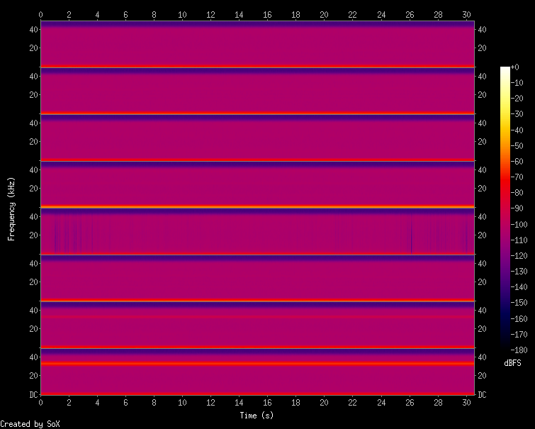
With the configuration above I get the following spectro:
But it looks like there’s no input signal (signal level bars are also empty while recording in terminal)
Thanks a lot for your test. Your aplay -l suggests the I2S device config is not working, only the acodec device is present. Also the channel numbers confirm that - 2ch DAC, 8ch ADC.
Probably some issue with the overlay, always a PITA to troubleshoot. The dtc command for listing the whole device tree has served me very well. Also serial port output, especially uboot listing what DTS and overlays were applied, eventually that an error occured.
I use a different DTS, using spdif transmitter/receiver codecs, do not know if available in your 4.4 kernel.
Does dmesg give any relevant info for the i2s_8ch_0 interface?
The i2s format applies to each data line, i.e. 8ch should be both OUT and IN.
Sorry my bad, have connected UART console and saw I misspelled one letter in DT overlay name. Now DT is in place but recording does not work for some reason:
rockpis:/home/rock# aplay -l
**** List of PLAYBACK Hardware Devices ****
card 0: Loopback [Loopback], device 0: Loopback PCM [Loopback PCM]
  Subdevices: 8/8
  Subdevice #0: subdevice #0
  Subdevice #1: subdevice #1
  Subdevice #2: subdevice #2
  Subdevice #3: subdevice #3
  Subdevice #4: subdevice #4
  Subdevice #5: subdevice #5
  Subdevice #6: subdevice #6
  Subdevice #7: subdevice #7
card 0: Loopback [Loopback], device 1: Loopback PCM [Loopback PCM]
  Subdevices: 8/8
  Subdevice #0: subdevice #0
  Subdevice #1: subdevice #1
  Subdevice #2: subdevice #2
  Subdevice #3: subdevice #3
  Subdevice #4: subdevice #4
  Subdevice #5: subdevice #5
  Subdevice #6: subdevice #6
  Subdevice #7: subdevice #7
card 1: multichcard [multi-ch-card], device 0: ff300000.i2s-dummy_codec dummy_codec-0 [ff300000.i2s-dummy_codec dummy_codec-0]
  Subdevices: 1/1
  Subdevice #0: subdevice #0
rockpis:/home/rock# tinypcminfo -D 1
Info for card 1, device 0:

PCM out:
      Access:	0x000009
   Format[0]:	0x000444
   Format[1]:	00000000
 Format Name:	S16_LE, S24_LE, S32_LE
   Subformat:	0x000001
        Rate:	min=8000Hz	max=192000Hz
    Channels:	min=2		max=8
 Sample bits:	min=16		max=32
 Period size:	min=8		max=65536
Period count:	min=2		max=16384

PCM in:
      Access:	0x000009
   Format[0]:	0x000444
   Format[1]:	00000000
 Format Name:	S16_LE, S24_LE, S32_LE
   Subformat:	0x000001
        Rate:	min=8000Hz	max=192000Hz
    Channels:	min=2		max=8
 Sample bits:	min=16		max=32
 Period size:	min=8		max=65536
Period count:	min=2		max=16384
rockpis:/home/rock# sox -V -r 96000 -c 8 -b 32 -t alsa hw:1 -n spectrogram -z 180 -w kaiser -d 40
sox:      SoX v14.4.2
sox FAIL formats: can't open input  `hw:1': snd_pcm_hw_params error: Invalid argument
Maybe arecord would tell more info about the specific parameter (hw_param has quite a few params). I like putting pv into the chain as the displayed flow rate directly shows if the I2S clock is correct (which is not always the case):
arecord -vv -r 96000 -c 8 -f S32_LE -D hw:1| pv > /dev/null
arecord -vv -r 96000 -c 8 -f S32_LE -D hw:1| pv > /dev/null
arecord: set_params:1456: Unable to install hw params:
ACCESS:  RW_INTERLEAVED
FORMAT:  S32_LE
SUBFORMAT:  STD
SAMPLE_BITS: 32
FRAME_BITS: 256
CHANNELS: 8
RATE: 96000
PERIOD_TIME: (42666 42667)
PERIOD_SIZE: 4096
PERIOD_BYTES: 131072
PERIODS: 4
BUFFER_TIME: (170666 170667)
BUFFER_SIZE: 16384
BUFFER_BYTES: 524288
TICK_TIME: 0
0.00 B 0:00:00 [0.00 B/s] [<=>
dmesg
[  184.858047]  ff300000.i2s-dummy_codec: ASoC: error at __soc_pcm_hw_params on ff300000.i2s-dummy_codec: -22
[  208.425534] clk_i2s0_8ch_rx_frac p_rate(49152000), rate(0), maybe invalid frequency setting!
[  208.425700] clk_i2s0_8ch_tx_frac p_rate(50176000), rate(0), maybe invalid frequency setting!
[  208.425761] clk_i2s0_8ch_rx_frac p_rate(49152000), rate(0), maybe invalid frequency setting!
[  208.425810] clk_i2s0_8ch_tx_frac p_rate(50176000), rate(0), maybe invalid frequency setting!
[  208.425862] rockchip-i2s-tdm ff300000.i2s: ASoC: error at snd_soc_dai_hw_params on ff300000.i2s: -22
[  208.425914]  ff300000.i2s-dummy_codec: ASoC: error at __soc_pcm_hw_params on ff300000.i2s-dummy_codec: -22
IIUC your i2s driver tries to set clk_i2s0_8ch_rx_frac and clk_i2s0_8ch_tx_frac clocks to zero frequency which correctly fails. I cannot find the error message “maybe invalid frequency setting” anywhere in https://github.com/radxa/kernel/blob/stable-4.4-rockpis sources, nor in any web search engine (e.g. https://www.google.com/search?q=“maybe+invalid+frequency+setting!” ) What source code was used for compiling your system?
Should you manage to find the line with that error message in your kernel sources, adding the dump_stack() command to that line block would help greatly to identify the culprit in your i2s driver source https://medium.com/@anamika.sanjay16/diving-deep-into-dump-stack-in-linux-kernel-development-32cc6339d506
But still it would be useful to identify your kernel source somewhere online so that we both can view it. Thanks!