It happens to be a random one on aliexpress
hrm, that one says 5v too, what does your sensors output show
It shows 12V 1A. Typically those barriers should work regardless of voltage because there is no regulators inside those adapters.
Its a cable not active and because it states you can use 5v doesn’t maen anything.
Start at scratch have a Rock5 with SD card only connect to hdmi and grab eith the Radxa debian or ubuntu image from the downloads page.
Grab etcher and flash the image.
Put in your rock5 use the adapter and make very sure the Gnd is the outside of the barrel.
If it doesn’t boot at that stage you may have problems.
Interesting, I thought the one above that you linked was the same, yet it says 5v. Need to test my voltage output it seems from the atx psu.
Wish I read this thread before buying a new 35w GaN with PD 3.0.
Should I have any hope this will ever work in the future or I might aswell return it to the store?
they say they will fix uboot so it works with regular ones. Or you can just buy their PS, like i did.
I was looking into this too.
GPIO is only 5v but given all of the confusion around USB-C PD I think it might be the way to go.
I’m currently looking to use something like this…
AC100v-240v to DC5v power brick.
Looks like it’s only 2 pins to wire it to the GPIO.
Only question is how many Amps/Watts do I need?
6A/30W or punch it all they way up to 75W.
No get a usb-c adapter, dupont headers I think might be only 1amp max? The crappy little jumper cables are really not up for even the SoC never mind possible pheripheral load.
It is not a Pi Zero its 3x+ a Pi4 with a lot more also going on.
Its 5v-20c on the usbc as there is an onboard buck that doesn’t care about PD
5v with possible total load starts to get silly ampages for even short distances to what you would think is thick cable.
12v is prob the min and still then you want a decent cable or cable your relatively cable length short.
Guess you could use 2x vcc & 2x gnd but still with 5v that is a lot of amps but guess it does free the usb-c.
You need to make up some custom jumpers with a bit more flesh than normal & not be bothered about the gpio pins being taken.
Or maybe use the POE or both as that is just VCC & GND (as dunno)?.
I am just lazy and a USB-C adapter seems much easier and less thought.
The headsers should be able to handel 3A per pin as far as I know, so for a single 2 wire connection it would be 5v3A. I know the GPIO has 4 points for power. I’m currently listening to 2 electrical engineers argue weather that means 2x 5v3A and 2 gnd or 3x 5v3A and 1 gnd. I’m going to find the pin-out diagram and show them later on
They seem to have come to a consensus one one part at least.
They both agree that as long as the voltage is 5v then the board should only draw the Amps that it needs and any modern day electronic shouldn’t allow itself to draw more power then the pins can handle.
Update:
We pulled an NVidia SBC we used for testing and it was powered through 4pins on a 40 pin GPIO using 2x 5v3A and 2x Gnd for a total of 5v6A(30w) of power. That looks like the theoretical limit the board can be powered over GPIO
The GPIO is acess past the onboard regulator and what you supply and how you supply it is down to you.
Prob (2x Vcc and 2x Gnd) for 2x 5v3A as it makes a circuit you need both (vcc & gnd) or its half. After a google dupont 2.54mm will take 3amp to my surprise but some others say 2.5 amp. Its prob the cheapo crimps we get on jumpers that are 1amp as sure I have seen 1amp somewhere and looking would expect something in that region.
If you know how much surface area is on one of those crimps then its cringe not crimp.
So yeah maybe 25-30 watt max decent connectors and cable but there is zero protection on GPIO power usually and with the Roc5b you do get a 2nd buck which is more than most.
This is what I am saying its just far easier to get a usb-c and safer but hey do whatever you wish.
Here is what adafruit say not me or your electricians
Today, I tried an Intel 8260 WiFi/BT combo M.2 card on my Rock 5B, with a known working USB-PD power supply (negotiates 20V, 1.5A). To my surprise, I suddenly had power issues. Checking the sensors command, it reported “0V, 0A”, and the actual measured VBUS was 5V. Removing the card - stable 20V again. Reinstalled - “0V 0A”.
Turns out, the I2C line connected to the E-key M.2 is the same one that runs to the USB-PD controller. This card happened to do something bad with the I2C bus (trying to talk on the same address, shorting the bus, injecting noise or a non-I2C signal into it, etc. - didn’t debug it any further).
Masked off the I2C pins with some tape. Card and PD now both work properly.
Moral of the story: if you get power issues after installing an M.2 device, or if you get “0V 0A”, check your I2C bus!
1 Like
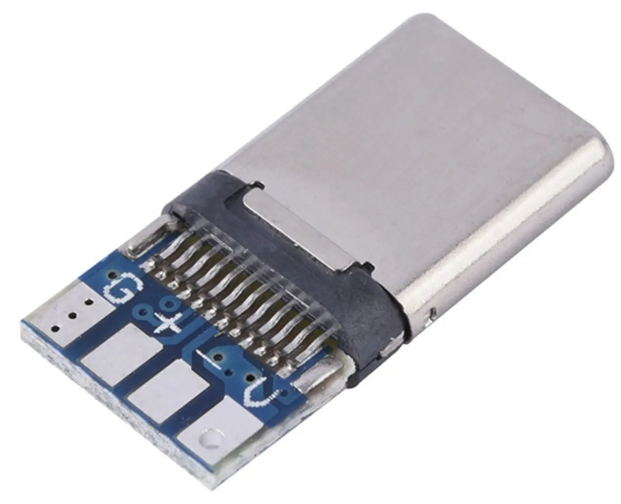
If it’s possible to use DC power supply 12v/5A with usb type c male connector
3141909563_w640_h640_type-c-papa-male.webp (26.2 KB)
jast melting two wire?
I think I got the same power situation when I installed 2T WD NVMe SSD.
Yep guess so as G & V are likely the vbus and really all that one of those USB-C adaptors does.
+/- I guess is data bus and not the same.
Adaptors do this already for you and its on you to make sure its correct otherwise.
I’ve used a UGREEN 65w GaN UK charger with success, sometimes it fails to boot once or twice, then just starts working. PD trigger cable also works, as does my Lenovo laptop 65w USB-C charger.
The voltage seems to be 20v. All in all, so far it works for me, using both the official Debian image and Armbian.
Ok so from my psu, the power is a solid 12.1v according to my multimeter, it doesn’t vary. So the barrel connector must be limiting it to 5v somehow or the sensors output is wrong? I’m not sure what to check here.
Masked off the I2C pins (58-61) with some tape.
According to the https://dl.radxa.com/rock5/5b/docs/hw/radxa_rock5b_v13_sch.pdf ,
Page Name: 06.PCIE-PCIE2.0_Slot-Ekey