you may need to ask Radxa for that i think  Stay tuned, I heard that they are coming to launch some new boards on rk3588 soon.
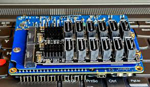
Radxa M.2 E key to SATA breakout card
It’s easier than You think,
@semi released everything needed to produce this board, just register on PCBWay, JLPCB, Elecrow or ITEAD, create project, upload project and just remember to change board thickness. There is option to assembly board, so You will get ready to use product.
Last time I checked everything was just few clicks.
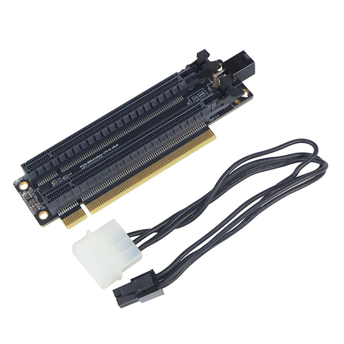
just one suggestion, the bifurcation board cannot provide sufficient power when using both of the nvme simultaneously. it’s would be nice if a power socket are provided on board. An usbc port with regulator would be ideal! 
I tested two 5-Port jmb585 controllers in m.2 format. I consistently get problems after a couple of hours, especially if I move around a lot of data or read a lot of data (test case is usually first moving a couple hundred gb from one drive to another and then scan a plex library). Timeouts, drives spinning down and spinning up, finally leading to readonly failing filesystems. I ruled out: cabling, drives, cooling of the jmb chip (still not sure, that’s a ridiculous small heatsink), and power supply.
@murpf Years ago I used these 5-port splitters on a x86_64 ITX motherboard connecting 3-5 drives on each JMB585. And I had exactly the same problems you describe. Whether it’s a linux driver problem or hardware I do not know. But I can tell it’s not related to the Rock 5A hardware or m.2 port.
The dual-port splitters JMB582 on the other hand have always worked perfectly for me in m.2 slots as well as in pci-express slots.
Hi There, I’m going to use the splitter card to connect a 5-port jmb585 and 10gbe simultaneously. I imagine they will require a lot of power to work together and the M.2 may not be able to pull them both together. Has anybody faced such a problem, what did you do to provide additional power supply?
Has anybody used this bifurcation board?
Would it work with ROCK 5B?
There is a power supply connector, yet it is not clear if it is IN or OUT (for SATA or something).
Instead of 5 port jmb585 use 6 port asm1166. Radxa recently added such card to their portfolio, I’m waiting for some details from @melo about it.
For best way to get 10Gbit (double!) and place for two m.2 sata cards checkout this link.
Also search for @seni bifurcation card here on forum.
This one probably will not work, its 16x to two 8x. Probably sata power is for one slot, the other one will get power from pci slot. There is only 5v/3v m.2 on rock 5B. This makes such setup big and bulky with ugly cabling.
You should be fine with Seni bifurcation board, one with sata ports and other with 10Gbit adapter.

@dominik
Thank you for your advice. Do you know any asm1166 with activity/error status pins for LEDs /UART?
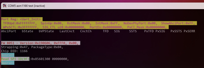
Most of ASM1166 m.2 cards comes with UART pins, but so far I could not get anything useful out of that,
My all four cards return:
I guess it’s interface used for some debug, or firmware upgrade,
there was no change when drive was connected or active,
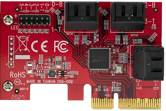
All of them have built in LED activity indicators. I think that those cards are not ready to connect UART with backplane and get any type of activity there, but for simple build You can either connect some fiber to LEDS or just remove those, solder wires (or some conectors) and LEDs whenever You need them .
If You need to connect board with backplane and activity leds still HBA card should work with that. One thick cable with four sata or eight sas channels + sgpio. Usually those cards have at least two mini sas connectors.
Can you recommend any ASM1166 M.2?
You can check the one from Radxa:
Jack, is it available anywhere to buy or when it will be expected?
I still have no response from @melo in radxa hexa sata m.2 card thread, some of those questions are rather important (like the one about heatsink and temperatures). Anybody else from @radxa may know about it?
On the other hand it may be better to get such card instead of some noname adapters with no docs and anything. Also the lack of heatsink may be better choice on some builds, check out card from this link - it has place for two nvme drives with large active cooler and heatsink, but no such card will fit there. I’m thinking about radxa sata card and possibility to desolder sata ports and activity leds, extend everything from card to panel.
I wish I could the one from radxa, but it don’t have UART pins - which I don’t know if they are somehow useful or not. Also some clarification is needed regarding card temperatures.
I have about four of those in m.2 format. Two with no version on them, one v1.2 and one v1.3, those have slightly improved LEDs (brighter), also slightly changed down plate (this is really needed element).
For sure regular pcie versions are much more durable. They have thick PCB and don’t bend easily. If Your build don’t have to be that compact then use something like that. Also you will get much larger heatsink.
Silvercrest guys seems to work sometime on ASM1166 firmware, same works on smaller cards.
The problem is that all existing options that I’ve managed to find don’t provide any hardware mechanism to control the backplane HDD activity/error LEDs which are typical for NAS cases (Here is mine: https://wiki.kobol.io/helios64/front-panel/ ). And I don’t see such a mechanism on the “Radxa M.2 to Hexa SATA Adapter”, there are no status pins, UART, SPI, GPIO… nothing but the SATA connectors. This is not an option for a NAS case.
SAS+SGPIO is a good option except that the boards are PCIe and bigger than any M.2 with SATA, and the SGPIO can’t be directly connected to the LEDs, it needs to be “decoded” and there is no simple way for that.
The best option that I see at the moment is * StarTech ASM1166 6P6G-PCIE-SATA-CARD
It has the LED activity pins (yet there are no ERROR status pins) and what seems to be SPI… but without any information what they can be used for. And I’m not sure if it is compatible with the ROCK 5B.
Probably You will not find anything that has such option in small m.2 format. It’s just not much space there for such thing. Some adapters have leds, so it’s quite easy to desolder them and replace with some kind of connectors, but still You will get only activity leds.
Some other idea is to use GPIO and read such state in system, some kind of script that pass those into You backplane, then You can keep compact size and get backplane to work. I don’t expect You will get anything at hardware level to match with helios backplane connector.
Those still can work via m.2, that’s why I asked about that in my topic about radxa hexa sata card.
For this the best option is to use compatible HBA card, cage, and backplane. Those should work and needed functionalities at hardware level. YEs, they are much bigger and Rock5B looks ridiculous with much bigger extension card.
This is simple LED header, directly connected to ASM1166 chip. Usually those are leds on board, they will light up on link, blink on activity. Most of SATA cards just have LEDs with that. You can wire up those directly to Your panel for activity leds.
For errors You will need something that know what is error and how to handle that. GPIO and simple script can do that. You can read smart status and turn on high state that will show error led on Your panel.
Yet again don’t expect any out of box solution for that as well as super compact m.2 card with such support.
HBA cards are designed to work with matching backplane, many work with SATA (and SAS), they carry sgpio signals on mini sas connector, but still this needs to be paired with right controller and software.
I also would love to get such feature for ASM1166 cards, but cuold not find any tech docs about lines found on some of those cards, but as far as I know there is UART (useless?) + i2c (unknown device).
Sorry for necroposting.
I tried to use this board RADXA M.2 E KEY TO SATA BREAKOUT BOARD with my Rock5b on armbian 24.x.x kernel version 6.1.x, but it does not see my hdd.
I have tried to install dto from two sources: part of armbian package, and compiled by armbian-add-overlay (with code from 5.0 kernel found in radx/kernel github).
Is it a way how I can see some logs to understand on what stage it’s not working?
Maybe we have some fresh instruction, because the one from radxa website is not working even on official Debian image there is no script mentioned in it.
Disclaimer: I’m not linux expert.
UPD: Added separate topic Radxa M.2 E key to SATA breakout card on Armbian. HDD is not visible - ROCK 5 Series / 5B/5B+ - Radxa Community
Would be much better to create fresh topic about it.
Use bundled sata2 overlay from armbian, I think I got this working on 5B few days ago.
Checkout dmesg for logs and sata keyword
@kwankiu @Semi A PCI switch chip such as ASM2812 would make all the sense in the world - it would allow you to do one or more SSD:s, and high speed Ethernet, all at peak speed, with the total bandwidth cap of 32gbit as only constraint.
With such a chip, having both 2, 3 and 4 M.2 22x80mm slots would make sense.
Has there been any work on such a card?
Such a card would make the Rock5B a lot more useful as computer.
I’d love to make the PCB i made using a packet switch like the ASM2812, but they don’t sell to private customers. There are a few alternative chips available on the market, but they typically cost upwards of 200 bucks, making it cheaper and easier to just use an m.2 to PCIE adapter and then use a PCIE card with such a chip.
Check out my thread about dual 10G ethernet + 2x m.2 on pcie 3.0/4x with rock 5. Such card needs some power and cooling, but such cards already are available and (almost working) on ARM.
This would not be that simple and small card. In short You will end up with something bigger and hotter than rock 5B board plus 2x more additional power consumption + quite significant cost.
Take a look at some efforts to get coral duap edge tpu to work. There is a project about that, it solves the problem, but board is about the price of coral adapter, so simply buying yet another one (maybe usb) will give the same result 
Cards with it is about $100-150, so low volume product will probably be more expensive as Rock 5B itself. Does it still make much sense? 
For sure this will be not that popular product. Cixin with a lot more pcie is maybe better idea and we may see smaller form factors there.


