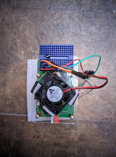
Possible to use 5V Relay module with GPIO?

Hi,

Background:
The Rock Pi RK3399 SOC can get hot while working. To help with cooling, I am trying to add small heatsink + fan. The fan is a bit loud though, and not needed all the time.

To automate, I am trying to use a relay to switch the fan using GPIO.

The issue:
I am using a 5V relay module with Active Low output (known to work with 3.3V as well). This relay works with my Raspberry Pi 3B.
However when I am using it with Rock Pi 4B, it is not able to switch the relay. Tried it with different pins, but same result.

Is it possible to use a 5V (Raspberry Pi 3 compatible) relay with the GPIO? Thanks.

Searching online, there are some ways to convert 3V and 3V3 signals to 5V:

I think the simplest (for me) would be to purchase a logic converter to convert the GPIO signals to 5V. It would require some soldering and connections to the relay.

You just need one simple and very cheap transistor to control the 5v signal with the 3v.

Try a 2n7000. Major online electronic component stores sell them for about $0.25 each INDIVIDUALLY, or Amazon or ebay you can get a bag of 100 of them for around $10.

Wire it like this;

+5v directly to the relay coil.
Other side of the relay coil to the DRAIN pin of the transistor.
SOURCE pin of the transistor to GND.
GATE pin of the transistor to the 3v GPIO.
** Do not try to put the transistor on the “high” side of the relay coil. It won’t work there. Has to be on the low side.

HOWEVER, there is potentially a better option;
Get yourself a 5V PWM fan. Wire +5 and GND into the red and black wires.
Connect the PWM wire (typically blue) to a GPIO.

PWM fans have a voltage divider in them, so the operating voltage will be anything above 2.5 volts. Now you can control the fan all the way from OFF to maximum by varying the PWM duty cycle. If you can’t figure out how to PWM it, you can just switch the GPIO on and off to switch the fan between maximum and minimum. If you can figure out how to work the PWM, then you can do something fancy, like varying the RPM based on the CPU temperature.

2 Likes

Hi aaditya!

I agree with libdroidman, you really should consider to use a transistor, so you can control the fan speed using a PWM signal.

The 2N2222 is a great one as it can drive up to 1A.
You can find this transistor in this $3 transistor kit: https://www.ebay.com/itm/153247367412

This tutorial is ideal for a start: https://www.instructables.com/id/PWM-Regulated-Fan-Based-on-CPU-Temperature-for-Ras/

1 Like

@lbdroidman I didnt know I could use a ready made 5V PWM fan!
Searching online, Noctua-NF-A4x20-5V-PWM seems to be option. I like it, especially the quiet part, but its not available locally and importing would be costly. Your simple instructions to connect the components are helpful.

@julien I didnt know I could make a PWM fan by using those components! That is indeed much better than operating the fan at full force. Noted and bookmarked.

I ordered some components today, would have added the required parts if I had known.

Thanks guys @lbdroidman and @julien, your suggestions are very helpful!

Yeah, that Noctua would definitely do it. But they do tend to be pretty expensive, and worse if you have to import them.

The downside to the 2n2222 is that its a BJT, which means you need to drive the right current to the base. Not terrible to calculate, but much simpler to slap in a FET and not have to worry about what the right size of resistor is.

1 Like

Hey @lbdroidman

I am trying to figure it this out in my head. One connection seems missing: the Data Input pin of the Relay.

Here is a crude diagram:

Rock Pi       Relay        Transistor
-------       -----        ----------

           |------------|
           |            |
Gnd <------|  Gnd ----| |---- S
                      |
5V ---------> 5V      |       G <--|
                      |            |
GPIO -----|   DIn(?)  |---->  D    |
          |                        |
          |------------------------|

Thanks.

I really can’t tell what you are trying to show with that diagram.

Relays don’t have data pins. They have coils. One side of the coil will be +5V, the other side GND. When power is applied to the coil, it creates an electromagnetic field that pulls the switch into the other position (on).

So like I said, you connect one side of the coil to +5, and you connect the other side of the coil to the transistor’s drain pin. The transistor’s source pin connects to GND, thus the circuit connects as this diagram;

+5 ==> A (Relay coil) B ==> D (Transistor) S ==> GND

  • Where A and B represent the two pins on the relay that are connected to its coil.

When the transistor switches on (by applying +3.3v to its GATE pin, not shown in the diagram above), the circuit is complete and the relay coil is energized.

Here’s a picture:

“Load” is the relay coil.
You do not need R1 on this type of GPIO pin.

1 Like

I meant a 5V relay module, like this. Sorry, I didnt realize that there is another type of relay which is similar but different. Will edit my post.

Ok, so on those “modules”, the relay is the part that says “songle” on it, which you now know how to drive directly without all the other nonsense on those boards. :slight_smile:

You see the jumper that says RY-VCC, VCC, GND? Take that jumper off. Put 5V to RY-VCC, put 3.3V to VCC, put GND to GND. Then hook GPIO pins DIRECTLY to IN1 and IN2.

When the GPIO is set LOW, the relay will switch ON. When the GPIO is set HIGH, the relay will switch OFF.

It may not work, however, because they have selected an inappropriately large value of resistor at R1/R4. For those optocouplers at 5V, those resistors should be about 190 ohms. They selected 1000 ohms, which means that the LED in the optocoupler isn’t running anywhere near as brightly as it should be. At 3.3V, it should be 105 ohms. So if it doesn’t work, I’d suggest changing those 2 resistors for 200 ohm, which should be enough to run it at 3.3v while still being safe at 5V.

Those resistors are standard 0805 sized surface mount, which is not terrible to work with by hand. However, as an alternative, you could also use a conventional radial resistor of about 250 ohm and just run it in parallel with the 1000 ohm surface mount resistor to bring you to the same value.

In that case, you can connect one side of the radial resistor to the PIN1 of the optocouplers (the part that says “817C” – pin 1 is marked by a DOT and has the square shaped pad), and the other side to one of the “VCC” pins.

OR, your final option is to wire it up the same way with a 2n7000, which also has the advantage of inverting the control logic, which means GPIO ON will correspond to RELAY ON. In this case, keep the RY-VCC --> VCC jumper in place. Hook the “IN1” or “IN2” pin to the DRAIN pin on the 2n7000, SOURCE pin of the 2n7000 to GND, and GATE pin of the 2n7000 to GPIO pin.

1 Like

I ordered components required for all 3 approaches. Initially meant to go for @lbdroidman’s approach to use transistor to convert 3V GPIO signal to 5V, but the connection diagrams went over my head. :slightly_smiling_face:

Review of approaches below:

1. Using Logic converter + relay

Didnt work for me. Tested both on Rock Pi 4 as well as Raspberry Pi 3. Maybe the component is faulty, or I made an error while soldering (newbie at it).
Not recommended due to large no of connections and soldering required.

2. Using 2n7000 transistor + relay
Have the components, but dunno how to connect them together.

3. Using 2n2222 transistor + 1K resistor + diode
This worked! The guide posted by @julien was simple to follow. Used a mini breadboard to connect the components. Worked on first try. Simplest and cheapest of all options. The breadboard connections are not rock steady, soldering can help if experienced. Instead of PWM I am using it in on off mode by connecting it via GPIO.

Thanks! :innocent:

I have the same situation here, I bought a 5V fan but I don’t want the fan to be on all the time. I am wondering if it wouldn´t be possible to plug the red to +5V and the blakc to GPIO2_A7(PIN #3) setting it as output with value 0.

In fact I’ve tried it without success. How much current the GPIO can source?

Anything wrong with my my code?
root@rockpi:/sys/class/gpio/gpio71# cat direction
out
root@rockpi:/sys/class/gpio/gpio71# cat direction ^C
root@rockpi:/sys/class/gpio/gpio71# cat value
0

Hi @rodvlopes,

Nope, certainly not! I have read that its possible to brick your Pi by making wrong connections, so would advise to research before trying!

To allow a 5V fan with 2 wires to be on and off, additional components are needed. These can include:

  • A relay that can switch at 3V as provided by RK3399 GPIO.
  • OR A circuit that consists of transistor, resistor, diode soldered together as shown in guide posted by Julien.

If you are a non technical user, i would suggest one of the following options:

Thanks @aaditya, I think the diode-transistor-resistor is my best bet. I’ll post the result as soon as I have implemented it.

1 Like

I Did it. It woks. I am using the 2N7000 transistor.

I just can’t PWM it. I am trying this:
root@rockpi:/sys/class/pwm/pwmchip0# echo 0 > export
-bash: echo: write error: Device or resource busy

Any ideia?

I believe PWM has to explicitly enabled via editing /boot/hw_intfc.conf

https://wiki.radxa.com/Rockpi4/hardware/devtree_overlays

I followed the instructions. Installed rockchip-fstab and rockpi4-dtbo, edited /boot/hw_intfc.conf to set pwm0 and pwm1 to on, but after a reboot I am still getting that device is busy.

root@rockpi:/sys/class/pwm/pwmchip0# cat npwm 
1
root@rockpi:/sys/class/pwm/pwmchip0# echo 0 > export
-bash: echo: write error: Device or resource busy

I believe /boot/hw_intfc.conf is being ignored. Is there anywhere else that could set this?

My image is Ubuntu Server 18.04

I dont know about it, would suggest to open a new topic.

Looks like you already did. :slight_smile:

1 Like

I am sharing the code of my fan-controller.

/*
    This program has been developed to run on the ROCKPI4 to control a 5V fan connected to any GPIO through a NPN transistor.
     
    to compile: gcc fanctl.c -o fanctl
    to install: install fanctl /usr/local/bin/
    to customize: change the definions below.
    to debug: fanctl debug
    to install as a service: vi /etc/systemd/system/fanctl.service 
      (with following content, then systemctl start fanctl.)
      
      [Unit]
      Description=Fan control based on cpu temperature

      [Service]
      Type=simple
      ExecStart=/usr/local/bin/fanctl

      [Install]
      WantedBy=multi-user.target
*/

#include <stdio.h>
#include <unistd.h>
#include <stdlib.h>

#define PINNUM "146"
#define PINVALUE_FILE "/sys/class/gpio/gpio" PINNUM "/value"
#define PINDIRECTION_FILE "/sys/class/gpio/gpio" PINNUM "/direction"
#define EXPORT_FILE "/sys/class/gpio/export"
#define TEMPERATURE_FILE "/sys/class/thermal/thermal_zone0/temp"
#define TEMPERATURE_THRESHOLD_ON  59000
#define TEMPERATURE_THRESHOLD_OFF 40000
 
int file_exist (char *fname) {
    return access( fname, F_OK ) != -1;
}

int is_pin_exported () {
    return file_exist (PINVALUE_FILE);
}

void export_pin () {
    FILE *fex, *fdir;
    fex = fopen(EXPORT_FILE, "w");
    fputs(PINNUM, fex);
    fclose(fex);
    fdir = fopen(PINDIRECTION_FILE, "w");
    fputs("out", fdir);
    fclose(fdir);
}

void switch_pin (int val) {
    FILE *fp;
    char str[5];
    sprintf(str, "%d", val);
    fp = fopen(PINVALUE_FILE, "w");
    fputs(str, fp);
    fclose(fp);
} 

int read_cpu_temperature () {
    FILE *fp;
    char str[5];
    int val;
    fp = fopen(TEMPERATURE_FILE, "r");
    fread(str, sizeof str, 1, fp);
    fclose(fp);
    val = atoi(str);
    return val;
}

int main (int argc, char *argv[]) {
    int debug = 0;
    int current_cpu_temp = 0;
    
    if (argc > 1) debug = 1; //any arguments enable debug mode

    debug && printf("CPU FAN Control Started on pin " PINNUM "\n");

    if (!is_pin_exported()) {
        export_pin();
    }

    while(1) {
        current_cpu_temp = read_cpu_temperature();

        debug && printf("Current CPU TEMP is %d\n", current_cpu_temp);
        if (current_cpu_temp > TEMPERATURE_THRESHOLD_ON) {
            switch_pin(1);
            debug && printf("on\n");
        }
        else if (current_cpu_temp < TEMPERATURE_THRESHOLD_OFF) {
            switch_pin(0);
            debug && printf("off\n");
        }
        usleep(500000); //500ms
    }

    return(0);

}
1 Like