Ok, so on those “modules”, the relay is the part that says “songle” on it, which you now know how to drive directly without all the other nonsense on those boards. 
You see the jumper that says RY-VCC, VCC, GND? Take that jumper off. Put 5V to RY-VCC, put 3.3V to VCC, put GND to GND. Then hook GPIO pins DIRECTLY to IN1 and IN2.
When the GPIO is set LOW, the relay will switch ON. When the GPIO is set HIGH, the relay will switch OFF.
It may not work, however, because they have selected an inappropriately large value of resistor at R1/R4. For those optocouplers at 5V, those resistors should be about 190 ohms. They selected 1000 ohms, which means that the LED in the optocoupler isn’t running anywhere near as brightly as it should be. At 3.3V, it should be 105 ohms. So if it doesn’t work, I’d suggest changing those 2 resistors for 200 ohm, which should be enough to run it at 3.3v while still being safe at 5V.
Those resistors are standard 0805 sized surface mount, which is not terrible to work with by hand. However, as an alternative, you could also use a conventional radial resistor of about 250 ohm and just run it in parallel with the 1000 ohm surface mount resistor to bring you to the same value.
In that case, you can connect one side of the radial resistor to the PIN1 of the optocouplers (the part that says “817C” – pin 1 is marked by a DOT and has the square shaped pad), and the other side to one of the “VCC” pins.
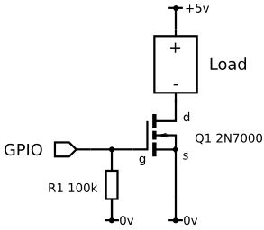
OR, your final option is to wire it up the same way with a 2n7000, which also has the advantage of inverting the control logic, which means GPIO ON will correspond to RELAY ON. In this case, keep the RY-VCC --> VCC jumper in place. Hook the “IN1” or “IN2” pin to the DRAIN pin on the 2n7000, SOURCE pin of the 2n7000 to GND, and GATE pin of the 2n7000 to GPIO pin.


