No SD card on CM3s in various carrier boards

I’m currently evaluating the CM3 for a customer while also working on my own carrier board. I have three CM3s (v1.31A): one with eMMC, booting the Radxa Debian image, plus two lower-end units with no eMMC or WiFi. I’ve been unable to get an actual Radxa CM3-IO board, and am working with various other carrier boards:

  • Official Raspberry Pi CM4 IO board
  • PINE64 SOQuartz carrier
  • PINE64 SOQuartz blade
  • Big Tree Tech Pi4B board

I’m not able to get any CM3 unit to talk to any SD card in any of the carrier boards. I’ve verified the SD card has 3.3V power, but the eMMC CM3 cannot see it once booted, and the non-eMMC CM3s cannot boot. PINE64 SOQuartz modules work fine in the same carriers with the same SD card brands.

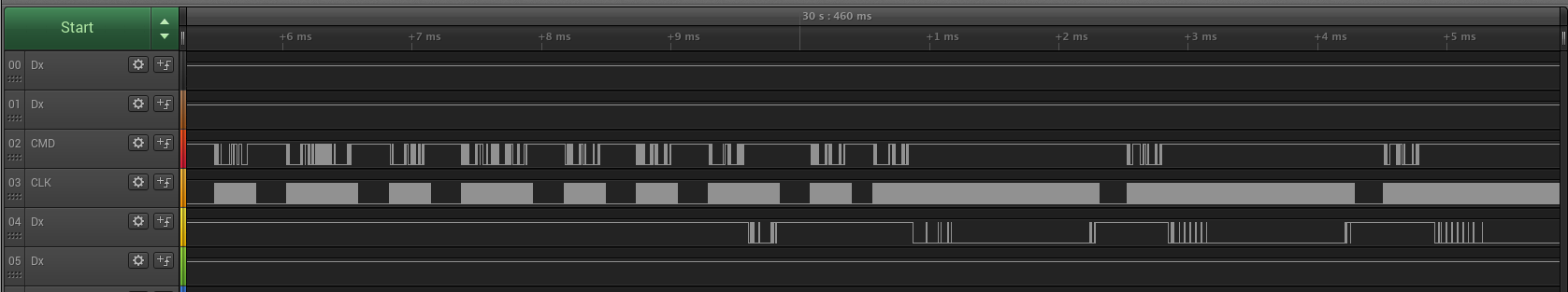
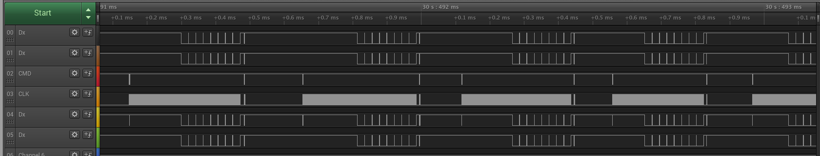
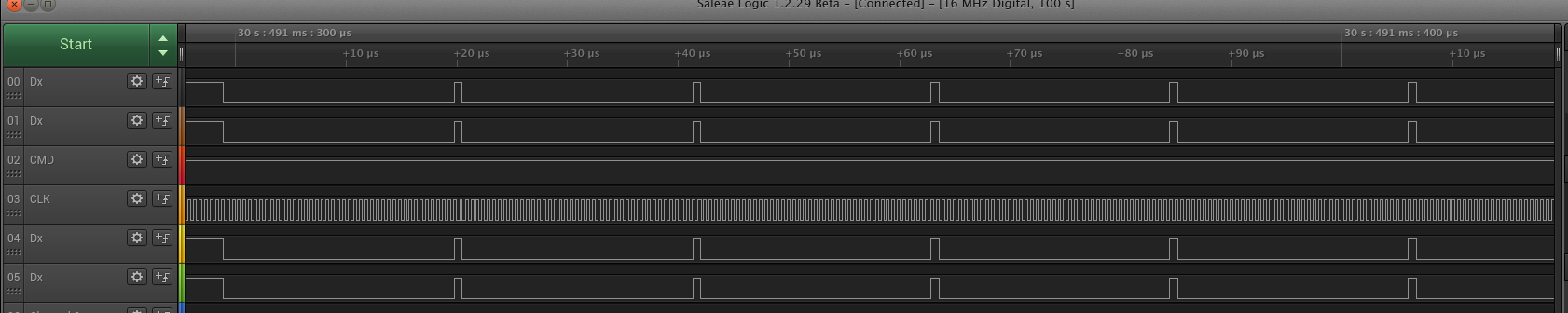
I note that a lot of designs including the Ras Pi IO board connect SD card detect to pin 76, though it’s marked as NC. The Ras Pi IO board is populated this way, and does not react to the card. I modified the Ras Pi IO board to connect the card detect so it pulls pin 76 low when a card is inserted, and now when I insert the card I get messages like this:

[  167.228071] mmc_host mmc1: Bus speed (slot 0) = 375000Hz (slot req 400000Hz, actual 375000HZ div = 0)
[  167.368033] mmc_host mmc1: Bus speed (slot 0) = 375000Hz (slot req 300000Hz, actual 187500HZ div = 1)
[  167.380890] mmc_host mmc1: Bus speed (slot 0) = 375000Hz (slot req 375000Hz, actual 375000HZ div = 0)
[  167.508036] mmc_host mmc1: Bus speed (slot 0) = 375000Hz (slot req 200000Hz, actual 187500HZ div = 1)
[  167.518593] mmc_host mmc1: Bus speed (slot 0) = 375000Hz (slot req 375000Hz, actual 375000HZ div = 0)
[  167.644703] mmc_host mmc1: Bus speed (slot 0) = 375000Hz (slot req 100000Hz, actual 93750HZ div = 2)
[  167.657560] mmc_host mmc1: Bus speed (slot 0) = 375000Hz (slot req 375000Hz, actual 375000HZ div = 0)

with Sandisk and Kingston cards, and this with Patriot:

[   27.213710] mmc_host mmc1: Bus speed (slot 0) = 375000Hz (slot req 400000Hz, actual 375000HZ div = 0)
[   27.251688] mmc1: error -110 whilst initialising SD card
[   27.370411] mmc_host mmc1: Bus speed (slot 0) = 375000Hz (slot req 300000Hz, actual 187500HZ div = 1)
[   27.383278] mmc_host mmc1: Bus speed (slot 0) = 375000Hz (slot req 375000Hz, actual 375000HZ div = 0)
[   27.412106] mmc1: error -110 whilst initialising SD card
[   27.530355] mmc_host mmc1: Bus speed (slot 0) = 375000Hz (slot req 200000Hz, actual 187500HZ div = 1)
[   27.543169] mmc_host mmc1: Bus speed (slot 0) = 375000Hz (slot req 375000Hz, actual 375000HZ div = 0)
[   27.568360] mmc1: error -110 whilst initialising SD card
[   27.686733] mmc_host mmc1: Bus speed (slot 0) = 375000Hz (slot req 100000Hz, actual 93750HZ div = 2)
[   27.699389] mmc_host mmc1: Bus speed (slot 0) = 375000Hz (slot req 375000Hz, actual 375000HZ div = 0)
[   27.725094] mmc1: error -110 whilst initialising SD card
[   33.760831] vcc_sd: disabling

With these modifications the SOQuartz still boots as expected.

Can you advise what I need to do to reliably boot the CM3 from SD card? My customer would like to select a module for their product, and I’d like to finish off my carrier board and get it into fab. Both need the option of booting a non-eMMC CM3 from SD card.

Thanks!

I like to know the solution to this to. Have not had any luck with any IO ports on any carrier board except for radxa’s own board.

Update: I added a devicetree overlay to add the broken-cd property to the SD card controller:

/** Overlay for debugging SD card on Radxa's Rock 3 CM3 image
 *
 * To use this dts:
 * - save this to a file named sdio.dtso
 * - apt-get install device-tree-compiler
 * - dtc -@ -I dts -O dtb -o sdio.dtbo sdio.dtso
 * - sudo cp gpio_pull-overlay.dtb /boot/overlays
 * - add this to the bootloader's overlay list
 */
/dts-v1/;
/plugin/;
/ {
	compatible = "radxa,radxa-cm3-io\0rockchip,rk3566";
	fragment@0 {
		target = <&sdmmc0>;
		__overlay__ {
			 broken-cd;
		};
	};
};

After this, the kernel can detect card insert/remove:

[  239.183494] mmc1: new high speed SDHC card at address 59b4
[  239.187602] mmcblk1: mmc1:59b4 SMI-S 7.61 GiB 
[  436.795892] mmc1: card 59b4 removed

All is still not well, since this is a ~32GB card reported as ~8GB, but it’s progress. I cabled the board to a Saleae logic analyzer, and can see the clock and command pins wiggling as expected. Clock speed is ~371KHz in this phase. On insert, there is traffic on one of the data pins:

Subsequent raw reads return all-zeros:

root@radxa-cm3-io:~# dd if=/dev/mmcblk1 count=1 | hexdump -C
00000000  00 00 00 00 00 00 00 00  00 00 00 00 00 00 00 00  |................|
1+0 records in
1+0 records out
*
00000200
512 bytes copied, 0.00176114 s, 291 kB/s

Interestingly, this is also the traffic on the bus, in read or write. Clock speed is 2MHz during the data phases:


The card I used is partitioned, so I should see a partition table in that first block. Writing random data to the card also shows all-zero on the Saleae, and has no effect when I examine it in another machine.

Did your problem get resolved ?

I have both “radxa-io-board” and “raspi-4-io-board(Official)”.
If I can get a concrete image-name of the problem you are having and the procedure for doing so,
I can confirm that by comparing the two boards.

My “cm3” is “v1.3” .
And configured with RAM:4GB & Wifi & eMMC:32GB & SPI-Flash.

* I am currently not using “eMMC”. The content is empty. (All “0x00”)


My case is the same as yours too, I could not boot from “SD-Card” at all.
But, After investigating for about 2-days, and I clarified the cause of the problem and took countermeasures, and now I can start it.

In my conclusion is that it is essential to modification the board (raspi-4-io-board: Official) in order to boot from the “SD-Card”.

Thanks for your reply, I still have no luck with CM3 in other boards. In each case (RPi IO and SOQuartz blade boards) I wired CM3 pin 76 (SDMMC0_DET_L) to the SD card detect, which seems to be active-low, with a 4k7 pullup to 3V3.

However I got my own design back from fab and built a couple on the weekend, where I designed in test points on SDMMC0_DET_L and the SD card’s detect. With a wire between and a pull-up to 3V3 it works perfectly with Radxa’s radxa-cm3-io-debian-bullseye-xfce4-arm64-20221101-0302-gpt.img image.

Possibly it’s a combination of SDMMC0_DET_L and SDMMC_PWREN nets? On my board the SD card is powered directly from the 3V3 net, since it’s the primary OS boot/root device… The other boards both have power switching for the SD card.

Regardless I’m able to make progress now. I’d suggest Radxa should update their docs to advise users that SD card-detect is mandatory to boot.

1 Like

My conclusion is that the following conditions must be met in order for the “IPL” inside the SOC to initiate the boot sequence from the SD-Card.

  1. The power of “SD-Card” must be on at boot time.
  2. The “SD-Card” detection signal (“SDMMC0_DET_L”) must be active at boot time.

Both of the above two conditions are required.

  1. is self-explanatory without explanation.
  2. Regarding this, I was wondering if “IPL” actually checking it,
    After some experimenting, I concluded that the “IPL” inside the “SOC” is checking the “SDMMC0_DET_L” signal.

Since you posted that you also own an “Official: Raspberry Pi CM4 IO board”,
I will use this as an example to explain in detail.
“Raspberry Pi Compute Module 4 IO Board” (cm4io-datasheet.pdf)

In addition, Radxa’s “IO Board”
It is highly recommended to also refer to “ROCK3 Compute Module IO Board” CM3-IO-V1.3-SCH.pdf.
(By comparing the two, the differences become clearer.)


Below is a specific example of countermeasures for the “Official: Raspberry Pi CM4 IO board”.

U18 (RT9742GGJ5): Short the “Pin 1” and “Pin 5” of the with a jumper wire.
Now the above condition 1) is always satisfied regardless of the state of the “SD_PWR_ON” signal.

R17 (unmounted part): Connect the “nf” side land of R17 to “GND” with a jumper wire.
R18 (unmounted part): Connect to “SDMMC0_DET_L” by placing a solder bridge across both lands.
Now condition 2) above is satisfied.

With these two modifications, “Official: Raspberry Pi CM4 IO board” can be started directly from “SD-Card”.
* At least in my case…

The point to pay attention to is the active level of the above two signals.

Looking at the circuit diagram,
The “Official: Raspberry Pi CM4 IO board” expects both signals to be “Active H”.
(Actually, “SDMMC0_DET_L” is not connected due to parts not mounted -> always “H” due to Pull-Up resistor on CM3 -> “SD-Card” not inserted)

On the other hand,
“ROCK3 Compute Module IO Board” expects both signals to be “Active L”.
(Actually, the power supply of “SD-Card” is always “Power ON” due to parts not mounted)

It is important to be aware of this difference between the two boards, rather than simply connecting the signals.


What follows is my subjective opinion on this matter.
Modification of the board is relatively easy with the “Official Raspberry Pi CM4 IO board”.
However, in the case of “WaveShare CM4-IO-BASE”, which has many problem reports,
Modification of item 2) is extremely difficult, and for most people it will be impossible.

Another problem is that the “Wiki” only mentions the case of booting from “eMMC”.
Everyone would think that if can boot from the optional “eMMC” media, we should be able to boot from the basic media “SD-Card” as well.
However, the reality is different from everyone’s expectations.
If it’s a variant with “eMMC”, a workaround would be possible, but if it’s not, there’s no way to deal with it.

It’s terrible.

Thanks again for your reply, I further modified the Raspberry Pi CM4 IO board to match (remove and bypass U18), and can now boot a non-eMMC CM3 module from SD card.

Agree with you it’s a relatively simple fix, and the documentation should be fixed.

Hi t4_4t,

Many thanks for your message. With the mods you said, now the following messages are printed in the dmesg.

[ 3071.171031] mmc_host mmc1: Bus speed (slot 0) = 375000Hz (slot req 300000Hz, actual 187500HZ div = 1)
[ 3071.183906] mmc_host mmc1: Bus speed (slot 0) = 375000Hz (slot req 375000Hz, actual 375000HZ div = 0)
[ 3071.314249] mmc_host mmc1: Bus speed (slot 0) = 375000Hz (slot req 200000Hz, actual 187500HZ div = 1)
[ 3071.326907] mmc_host mmc1: Bus speed (slot 0) = 375000Hz (slot req 375000Hz, actual 375000HZ div = 0)
[ 3071.454372] mmc_host mmc1: Bus speed (slot 0) = 375000Hz (slot req 100000Hz, actual 93750HZ div = 2)
[ 3071.467237] mmc_host mmc1: Bus speed (slot 0) = 375000Hz (slot req 375000Hz, actual 375000HZ div = 0)

But, anyone has tried to access to the sd card an use it as a disk?

I cannot see the sdcar neither in /dev or doing lsblk -l

root@radxa-cm3-io:/home/rock# lsblk -l
NAME         MAJ:MIN RM  SIZE RO TYPE MOUNTPOINT
mmcblk0      179:0    0 14.6G  0 disk
mmcblk0p1    179:1    0  512M  0 part /boot
mmcblk0p2    179:2    0   14G  0 part /
mmcblk0boot0 179:32   0    4M  1 disk
mmcblk0boot1 179:64   0    4M  1 disk

I would need to access to the sdcard to store some files there as logging memory.

Many thanks.

Regards,

I don’t know what kind of board you are using, but the “Radxa CM3-IO board” works fine.
However, I already pointed out, this board has a problem.
Cm3-io-board, “sd-cards” issues

In short, This board cannot use “UHS-Mode” with standard “SD-Card”.
This problem depends on the “OS(Kernel)” you are using.

If the kernel you are using is applicable, you need to either disable the corresponding item in the device tree or fix the board error.

I’ve tried with different boards. Radxa CM3 IO board and Raspberry Pi CM4 IO board with the mods you said.

Both are showing the messages in the desmg but nothing appears in /dev or disk.

The image I’m using is the last debian image from Radxa.

Thanks!

Boot priority of SOC(RK356x) is in order of “SPI-Flash -> eMMC -> SD-Card”.
So as long as the eMMC has bootable data, the image written to the SD-Card will be ignored.

I recommend booting from the SD-Card image while holding down the eMMC disable button on the “CM3-Module”.

As reported in the title of this thread and also in other threads
With the “Radxa CM3 IO board”, we don’t need to modify the board to boot from the SD card.

This does not match your report.

Hi t4_4t, my Radxa CM3 is not booting from SD with the Radxa CM3 IO Board. We can continue the discussion here CM3 wont boot from MicroSD - ROCK 3 Series / CM3 - Radxa Forum. But I’ve tried holding the golden button while powering the Radxa and nothing happens. The green LED of Radxa CM3 module never flashes green and only the red led near the HDMI connector stais on.

The board that I’ve modified to make the SD working is a Raspberry PI CM4 IO Board, not the Radxa. But on both boards, I am seein the “mmc_host mmc1: Bus speed (slot 0) = 375000Hz” message on the dmesg when I plug the SD card.

But later on, I cannot see any kind of devices on /dev to be mounted as a disk.

Thanks for your help.

In both cases, it is speculated that the “SD-Card” power supply line is suspect.
For “Raspberry Pi Compute Module 4 IO Board”, the following node on the schematic
SD_PWR: C5(10uF)

In the case of “ROCK3 Compute Module IO Board”, the following node on the schematic
VCC3V3_SD_1: C4/C5/C6/C7

I recommend observing the above node directly.

If there is no problem with the power control part of “SD-Card”, the voltage of +3.3v should be observed on both power nodes.

And if the “SD-Card” is properly powered,
Immediately after booting (about 1-2 seconds), the following message should be output from the serial console.


DDR Version V1.xx 202xxxxx
ln
ddrconfig: 0
LP4 MR14: 0x4d
LPDDR4, 324MHz
BW=32 Col=10 Bk=8 CS0 Row=17 CS=1 Die BW=16 Size=4096MB
tdqss: cs0 dqs0: 361ps, dqs1: 289ps, dqs2: 337ps, dqs3: 217ps,
...

The power node voltage of “SD-Card” is the correct value, But nothing output from the serial console.

If in such a above situation, I can’t think of an effective method other than directly investigating the actual thing.

I have a Radxa CM3 v1.31A without eMMC, which I had hoped to use in Raspberry Pi CM4 carrier board. I haven’t been able to boot it, and then I saw this thread. Do I understand it correctly, that due to a massive fuck-up on Radxa’s part, the Radxa CM3 is not actually compatible with RPi CM4 carrier boards?!