Introduce the Radxa Zero

Hello Guys,
I hope that you can help me out . I have just received two D1 radxa zeros , 1GB RAM and no eMMC only microSD. I am planning to use them in my volumio project , connecting the DAC over I2S .

My immediate problem is trying to boot the zeros . I have tried both Twister and Manjaro from the latest links above , and neither of them boots from the microSD on power up.

What I get when using minicom over serial is this:

G12A:BL:0253b8:61aa2d;FEAT:E0F83180:2000;POC:F;RCY:0;EMMC:800;NAND:81;SD?:0;SD:0;READ:0;CHK:1F;USB:8;0.0

And after that no progress at all . Looking at the github rs102 documentation page, it seems that this should only be happening after pressing the USB boot button on the underside of the board . However in my case both zero boards are doing the exact same thing, and button is not being pressed .

The lsusb printout does show , Amlogic device as if USB boot is active:

[root@hparch user]# lsusb
Bus 002 Device 003: ID 0a5c:21e1 Broadcom Corp. HP Portable SoftSailing
Bus 002 Device 002: ID 8087:0024 Intel Corp. Integrated Rate Matching Hub
Bus 002 Device 001: ID 1d6b:0002 Linux Foundation 2.0 root hub
Bus 001 Device 004: ID 1bcf:2c03 Sunplus Innovation Technology Inc. HP HD Webcam [Fixed]
Bus 001 Device 022: ID 1b8e:c003 Amlogic, Inc. GX-CHIP
Bus 001 Device 003: ID 138a:003d Validity Sensors, Inc. VFS491
Bus 001 Device 002: ID 8087:0024 Intel Corp. Integrated Rate Matching Hub
Bus 001 Device 001: ID 1d6b:0002 Linux Foundation 2.0 root hub
Bus 004 Device 001: ID 1d6b:0003 Linux Foundation 3.0 root hub
Bus 003 Device 002: ID 0403:6001 Future Technology Devices International, Ltd FT232 Serial (UART) IC
Bus 003 Device 001: ID 1d6b:0002 Linux Foundation 2.0 root hub
[root@hparch user]#

The only workaround I have found to boot from the microSD card so far , is to use the boot-g12.py script and load the u-boot.bin file I have downloaded from dl.radxa, into the board:

[root@hparch user]# boot-g12.py u-boot.bin
Firmware Version :
ROM: 3.2 Stage: 0.0
Need Password: 0 Password OK: 1
Writing u-boot.bin at 0xfffa0000…
[DONE]
Running at 0xfffa0000…
[DONE]
AMLC dataSize=16384, offset=65536, seq=0…
[DONE]
AMLC dataSize=49152, offset=393216, seq=1…
[DONE]
AMLC dataSize=16384, offset=229376, seq=2…
[DONE]
AMLC dataSize=49152, offset=245760, seq=3…
[DONE]
AMLC dataSize=16384, offset=65536, seq=4…
[DONE]
AMLC dataSize=49152, offset=393216, seq=5…
[DONE]
AMLC dataSize=16384, offset=229376, seq=6…
[DONE]
AMLC dataSize=49152, offset=245760, seq=7…
[DONE]
AMLC dataSize=49152, offset=294912, seq=8…
[DONE]
AMLC dataSize=16384, offset=65536, seq=9…
[DONE]
AMLC dataSize=1400176, offset=81920, seq=10…
[DONE]
[BL2 END]
[root@hparch user]#

Once that is done , then the zeros will boot from the microSD card , for both Twister and Manjaro .

I would like to use the zeros in my volumio radio , but if everytime i switch it off , I then need to log in via the USB and serial to manually run in the u-boot , to make them work , that’s not going to work for me.

So I need a better fix . Is my problem the lack of u-boot in the images ? Do I need to dd the u-boot into the SD cards , post image installation ? If so please advise the correct commands .

Or is my problem that the zeros are stuck permanently in USB boot mode ? If so how do I resolve this ? Is it a HW problem - a defect from the factory , or is it something I can correct in software/firmware? If so please advise procedure to resolve .
Much appreciate your help .

Best Regards
Mil

P.S.
Happy to run any commands , and get any prints needed .

I think a read through this sort of explains things.

If you put a usb tty serial console on the radxa zero as in https://github.com/radxa/documentation/tree/master/rs102

You can see uboot is loading but failing so its software but confused to how to progress with uboot.sd.boot.bin and which and what tree of u-boot we should use.

I have a 512mb and the same and its all non eMMC versions prob due to the closed source binary blobs of Amlogic that Baylibre and others have done so much great work reverse engineering.

I purchased a 2gb so I can have I can have a comparison and awaiting delivery but expecting that maybe someone will hack a solution.

You have mainline u-boot with https://u-boot.readthedocs.io/en/latest/board/amlogic/sei510.html as apart from ethernet the s905x2 is near identical to s905y2

As opposed to https://github.com/angerman/meson64-tools and pretty sure someone will sort it out soon as has been accomplished on other amlogic boards or it will be eMMC only.

At a guess the current uboot uses the version from 2015.01 and has a custom eMMC partition format based on NAND and when flashing SD its why we are getting messages on corrupt partitions.

So just downloading u-boot.bin.sd.bin and using DD is not going to work with a custom partition format maybe?

@sven posted the console info in this thread

or there is a an error in the u-boot dts config for the SD card that is correct in the mainline kernel?

@jack ?

I haven’t done much as still waiting for a eMMC version but have to say I am mighty confused on what u-boot or sources should be used?

Isn’t blx_fix.sh supposed to cut and compress the binaries so they do fit in the reserved memory area?

@mara might get it cracked with a slackware minimal image but is still waiting for a board.

Hi Jack and members of the Radxa Zero Team,

My name is Jeroen Wolf,
a 47 year old Dutch electronics and retro (handheld) gaming entouchiast from the Netherlands, Europe.

I’m in the process of designing my own retro handheld gaming system (a long lived dream om mine).
After countless electronic de-tours I finaly have a good work-flow and design for my clamshell handheld project.

I have an Electronics and Linux/JAVA/PHP/Python degree and I am (next to programming) a sucker for 8-bit (C64/NES) and 16-bit (Amiga/SNES) games. Next to retro gaming, I’m also very fond of ScummVM (point and click) adventures: https://www.scummvm.org like Money Island, Day of the Tentacle, Maniac Mansion, Simon the Sorcerer, Broken Sword.

It’s for these games, in combination with a clock radio (wake-up alarm for your side-table) + media function I want to design my handheld. I’m hoping to supply working models for my favourite YouTube’ers like ETA Prime, Retro Game Corps, Sonic Love, Retro Dodo and ExplainingComputers thus hoping to get my target audience excited for the kickstarter project I’m planning.

For my handheld project I researched several SBC (Single Board Computer) solutions, I looked into:

  • The Orange Pi Zero2 (4x 1.5 GHz Cortex-A53 CPU / Mali G31 MP2 GPU / 1GB DDR3 RAM)
  • The Banana Pi M2 Zero (4x 1.2 GHz Cortex-A7 CPU / Mali 400 MP2 GPU / 512MB DDR3 RAM)
  • The Lichee Pi Zero (1x 1.2 GHz Cortex-A7 CPU / Mali 400 GPU / 64 MB DDR2 RAM)

All SBC boards will probably more-or-less function,
but the main problem was (lack of) power (Pi zero/Banana Pi M2 Zero) or size (Orange Pi Zero2) for my design.

CPU/GPU/RAM-wise and certaintly size-wise your SBC should be a perfect candidate.

I have a question. When will this device be availible for the public and is it possible for me to implement your SBC into my (commercially) hardware design? Is it for example possible to try-out this product. This would help me out with reducing production time.
I want to use the Batocera distro (OS) in combination with my own controls / IPS screen.

I hope to hear from you.
All the best, Jeroen (from the Netherlands, Europe).

5 Likes

Hi all,
The GPIO header on the Radxa Zero, is this compatible (read, is this the same) as the raspberry Pi GPIO?? I want to use the 4 inch 720x720 @60fps IPS (see link above) but can this work?

Cheers, Jeroen

DPI interface nope, Zero is HDMI.

http://www.lcdwiki.com/Main_Page#Raspberry_Pi_HDMI_Display

Also the s905y2 packs a lot of punch for its size but is still fairly limited even if the 4x a53 and the mali g31-mp2 does give it reasonable performance.
Would be great if the MPI3508 also came with right angle 26pin gpio header as spi is on board but might not be same pins (for touch screen).

Cost wise something like a http://www.lcdwiki.com/3.5inch_HDMI_Display-B might be about $15 and a more balanced match.

The header on the Radxa Zero its prob better to get without and fit a a 90’ header and use jumper leads to connect whilst having a micro-hdmi to hdmi stack adapter for both boards.
There are 7" 1024 x 600 hdmi for approx $30+ but maybe this is the 4" 800x480 supposedly 60hz and says IPS

1 Like

Hi can I have one that has any ram and storage

So when can we expect these to be available for purchase? Allnet seems to be completely sold out.

如果在国内怎么买呢??能给我网站吗?

@stuartiannaylor
Much appreciate your help . I followed your post from the other thread , and was able to get my 1GB zero with no eMMC and only microSD to boot by itself at powerup from the card.

It should be mentioned that the Twister and Manjaro images in the links at the top of the post are only suitable for eMMC boards . And that an additional procedure needs to be done to make the images boot on non eMMC boards . Thats what confused me , anyways .

This is what worked for me:

  • Download the Twister image from link at top of Post
  • Download the pre-prepared u-boot from dl.radxa:
    https://dl.radxa.com/zero/images/loader/u-boot.bin.sd.bin
  • Copy Twister image to SD card:
    dd if=Twister-OS_Armbian_Focal_20.10_xfce-rockpi-zero-beta2.img of=/dev/sdh bs=1M status=progress
  • After this is finished , copy the downloaded u-boot.bin.sd.bin to the SD card (in two steps):
    dd if=u-boot.bin.sd.bin of=/dev/sdh conv=fsync,notrunc bs=1 count=444
    dd if=u-boot.bin.sd.bin of=/dev/sdh conv=fsync,notrunc bs=512 skip=1 seek=1
    According to Jack , the reason why u-boot installation is done in two steps , is to make it straddle the MBR block .

Mil

Can the 40Pin GPIO be used as RGB-LCD output?

Radxa Zero is hdmi only and doesn’t have dsi, slower displays such as spi or i2c the interface is likely on the pin mux but might not be the same (use jumper wires).
Seems so far no GPIO pin mux has been published as confused to I2S/DAC which for others is equally important.

@jack Do we have a GPIO pin mux?

Typical :slight_smile: As my 512mb still fails to boot but really I should go hunting for my serial console and find out why?
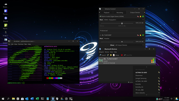
@sven seems to of got his booting :confused:

Yes, TwisterOS booting nicely for me (512mb with sdcard). Thanks to Mil and stuartiannaylor for the help and steps.
How are we looking with wifi, anyone got it to work?

1 Like

WIFI works out-of-the-box witn Zero 4Gb/32Gb eMMC model(w/ WiFi5/BT5 chip). Never tried w/ WiFi4/BT4 from entry level Zeroes.

BTW, We have a newest version(Beta3) of TwisterOS for Zero Board, you can download it from here:
https://drive.google.com/file/d/1UTganq1rdTF8H5GIB1uw2OBOfdaMk3uT/view?usp=sharing

Don’t forget to resize partition by either clicking on “Resize OS Partition” icon on desktop or using included gnome-disks or gparted utility, it won’t auto-resize on first boot. Otherwise, it won’t allow you to run update/upgrades via CLI.
Username: pi
Password: root0815

2 Likes

$45 USD? That is awesome.
I was on the fence about adding one, but that is SOLD!!!

Is Ubuntu or Debian compatible with this board?

Hi there! Is it possible to connect camera with CSI interface to this board? Can I buy some module or something else?

Just loaded up beta3 in my 1GB SDcard zero . Noticed a move from firefox to vivaldi .
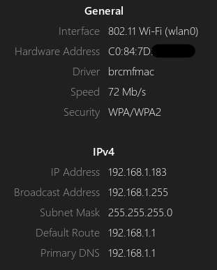
The WIFI works out of the box . Here is a screenshot , I have it on 2.4 GHz:

Screenshot_2021-08-02_08-12-41

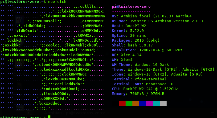
The neofetch info is:

By the way this post is being done from the zero , on vivaldi and wifi .

Next step is to identify the I2S pins for my pcm5102 based DAC , and then volumio .

Best Regards
Mil

3 Likes

I2S explorations on the 1GB zero:
There are according to the datasheet 2 TDM interfaces: TDMA and TDMB .
TDMA seems to be a smaller interface which apart from clock pins, has 2 data pins: D0 and D1 .
TDMB is a bit larger . It has aside form clock pins , 4 data pins: D0, D1, D2, D3 .

That’s interesting, I wander why the difference . Anyway .Here is how it possibly looks:

TDMA , needs to be put into Function1 to expose the I2S pins , as the pins are multi functional , depending on the config needed .

image

According to one note in the cct diagram , it suggests that D1 may be an input while the D0 is an output.
This would then make I2S interfaces Data, LRCK and BCLK appear on pins 12, 16 and 13 respectively.

TDMB , needs to be put into Function 5 , to expose its I2S pins , as the functionality is shared by jtag and other things .

image

The other interesting thing on the datasheet , TDMA goes via a UM3204 4-Bit Bidirectional Voltage-Level Translator , from the CPU/SOC to the GPIO connector 8601 .

I did not notice a similar thing with TDMB . Also this interface to me seems oddly drawn in the cct diagram , so I am not 100% sure that pins 31 and 33 are fully connected at the 8601 GPIO end . This would need examination of the hardware .

This is all I can see from the datasheet and the cct diagrams . If I have made any errors , please correct me .

Best Regards
Mil

Refer the sch for the pin mux for now:

https://dl.radxa.com/zero/docs/hw/

We will work on the pinout table soon.

1 Like