Input voltage limits

True :slight_smile:

If I shoot for efficient I want at least 95%, better 97% (or better). 90% is ok-ish, but keep in mind that those are the manufacturers claims. I don’t know how much effort they put it to produce those numbers and how hard it would be to re-produce them in your own design.
I suspect that the cheap DC-DC converter modules are optimised for minimal PCB space and therefore are probably not the best in terms of efficiency. Additionally you probably have … let’s call it “questionable components” (inductors, capacitors, diodes) where I also suspect that they are not optimized for maximum efficiency.

If I want an efficient DC-DC I would at least go for something synchonously rectified.

Those chinese modules don’t look all that bad, really. The main thing I don’t like about them is that they have much smaller input capacitors than the datasheet recommends. I’ve actually used LM2596 on some of my own boards, but the fixed version and the amazingly low efficiency 3.3v version, BUT, my input comes from a 24VAC transformer so maximizing the efficiency wasn’t all that critical of a parameter.

It would be interesting to see what the actual efficiency comes out at (of the amazon boards). Maybe I’ll measure it one of these days if I’m bored.

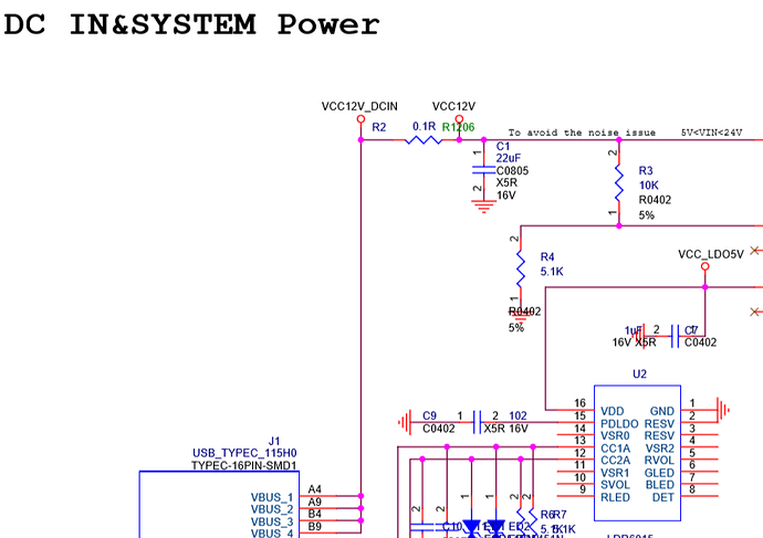
Ok, the schematic is quite funny, because the PD controller, LDR6015, has hardly any components attached to it. The datasheet doesn’t mention anything about pullups or pulldown, but I assume the pins responsible for selecting the Power Delivery Option have pull downs. The datasheet says, if all select pins are low, the LDR6015 selects the highest Power Option available. On my power supply this means 20V, which it actually does.

I guess I have to rework the EN-pin of the NB679, if it is actually still working :open_mouth:

Anyway, I can report that you can safely pass 20V into the USB port :slight_smile:

Hi,
can I also work with 24V?
I only have 24V and I don’t want to work with this LM because it only has max. 3A can. which is not enough in my case. since I need min 4A for the rest of the hardware that is installed. If the 24V goes I save a lot of work on my development board

Hi there,
To work with 20 or 24 V input voltage, only C1 has to be replaced, since it is currently only 16 V stable. The chip itself can be up to 28 V, so in my opinion it shouldn’t be a problem?

Here is an answer from @jack of Radxa Team: “you can power from the type C port with dummy 12V, up to 20V”.
Another quote from here: “Some dummy 9V or 12V adapter will work. … For QC, currently we select 9V because it’s the most common. For PD, we request 20V first, if not then 15V, then 12V, then 9V.”

I wonder who are wrong - you or @jack?

According to their data sheet, C1 22µF is only designed for 16V in the voltage section. So the question arises how it should endure 20V. hence the question again.
it may be that it goes with 20V, but how long is that good. I do not want to grill the part.

1 Like

It would be nice if they provided a BOM for it. While it does make mention of the capacitor’s specs on the schematic, it isn’t clear what the actual components are without the BOM. It could ship with a higher voltage capacitor. The Rock960 version (96boards) does come with a BOM which identifies its equivalent cap as a 25V. HOWEVER, there are significant differences in this area between the 960 and the pi versions, so that doesn’t imply anything about the pi. And further, its nice to have a little bit more slack between the actual voltage and the capacitor’s rating. I’d want to have a 50V cap in that location for running 24V to it.

96boards uses a barrel jack for power, and specs the input for the range 6.5-18V.

If the 24V power supply is known to be good and stable, you could also simply remove C1.

Is there something you are trying to say?

I am just reading the datasheet of the NB679, the schematic provided by Radxa and calculating the voltage over a voltage divider. If you’ve spotted a mistake I made in either of those, please let me know.

As I said, I’ve powered the Rock Pi 4 with a PD source at 20V. It worked for a couple of weeks.

That said, I’ve not checked if the schematic actually matches the board. @ingo also makes a good point, as to why 20V (or 24V) might work in the short term, but not in the long run. But @lbdroidman is also right: We don’t know the spec of the part on the actual board.

No, it’s not. Just a question to know. :slight_smile: It’s important to me.
I honestly think you are right.
But @jack is from Radxa Team. And I wonder why did he say about power for Rock Pi 4 up to 20V without any warning.

Oh, then I misinterpreted. Sorry.

It could be components on the board don’t match the schematic – then we would both right.

I tried powering the Rock Pi 4 with 20V and it worked.

I don’t think the issue with the resistor divider will fry the Rock Pi immediately, but rather it will have a long-term impact. It might also be that the NB679 will break under high load (high thermal stress) with additional thermal load from the increased input current into the EN pin.

Maybe the NB679 will even be fine under those stresses :man_shrugging:t2:.

I grilled the rockpi yesterday, 24V usb c plug and chip is scrap.

Which chip? The NB679 or the RK3399?

24V. Limit is 20V. HMMMM.

It was said multiple times here, that users even unsure, that 20V is alright for RockPi and here you are. Using 24V.

Like, why? Tell me, why?

With EN connected to VCC via a 10/5.1 Ohm divider, and EN max voltage being 4.5V, my calculation says that VCC max is not 9V but 4.5/5.1*(5.1+10) = 13.32V

I am just saying this because i wanted to power the rockpi4 from a PC power supply 12V line, so that i can more safely power 2.5" HDD attached to the rockpi4 USB3 ports. Should be a sae setup, also the radxa diagram has labelled VCC with 12V.

Alas, no help for when you want to run it with > 20V.

the nb679, C1 removed. R3, R4 Adapted to 24V
Since I want to use it as a PLC, it must be 24V fixed.
9v, 12V are not an advantage as PLC operation.

Correct. AFAICT 12V operation is totally fine.

C1 removed, not replaced? Doesn’t seem like a good idea to me. You need C1. Read page 15 ff. of the NB679 datasheet.

Is R1 fuckered or does it still work?

What voltage divider did you use? Between 1.4V to 1.8V on the EN pin will enable USM mode. Not sure if that would interefere with something (it shouldn’t, but …).

I need a pi that is 24V fixed, since the hardware then only works with 24v.
“B&R X64” bus system.
The Pi is unfortunately in the press.
Sorry my english is a bit bad

Understand the purpose of that capacitor, its there to handle the high but discontinuous current demands of the converter. A good quality power supply and low impedance wires, and that capacitor isn’t all that important. Its much more important for power supplies that are marginal, or wires that are relatively high impedance.

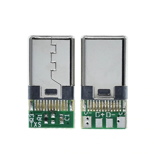
I confirm applying 20V through USB-C with a connector breakout board like the one


makes some damage. VCC12V became shorted to ground by NB679GD. My board is Rock PI 4C v1.2. Firstly, I thought that capacitor C90002 was shorted due to its voltage rating of 16V. But it turns out it was the NB679GD that was faulty. The only explanation I see is that the voltage divider formed by R90006 and R90315 apply around 6.75V on pin EN at 20V for VIN. EN pin is rated for 4.5V max. A better design would have been to replace R90315 with a 3.3V zener.

1 Like