
Would it be possible to power the Rock Pi 4 directly from a 6S, 22v nominal, 25.2v peak LiPo battery? What is the input voltage limit?
Input voltage limits
Short answer: No, at least not without changing the board.
Long answer:
USB-PD does max 20V, but only after a configuration change of the connected USB C/PD port. Technically 22V nominal/25.2V peak is over that.
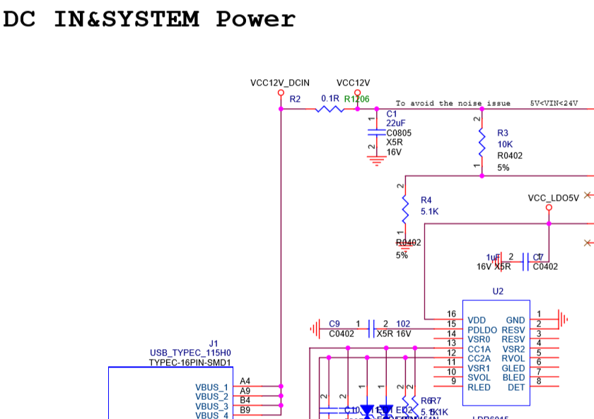
However, the input buck converter is a NB679 with a 5-24V input, with an absolute maximum of 28V. While your peak voltage is still more then the recommended voltage range (which I would not exceed), it is within the Absolute Maximum Ratings of the converter. From that it would work.
HOWEVER, the NB679 pin EN is connected via a 10k/5k resistor divider to the input voltage. According to the datasheet the maximum voltage on that pin is 4.5V. It follows that the maximum input voltage is limited to 9V. IMHO, you would need to change the input resistor divider to reliably use 20V input.
Additionally, USB PD does 20V (I guess that is what you want to use) only after a configuration change.
I would equip my battery pack with a DFP Power Delivery controller and a suitable converter. In a quick search I only found controllers for 1S LiPo batteries for power bank applications (some of which even support 12V output). Which doesn’t mean such controllers for other battery topologies don’t exist. I would not connect it directly, although you might get lucky.
2 Likes
Thanks for the detailed answer! I was indeed hoping to skip the extra DC-DC/ USB PD hardware by feeding directly into the buck. By the sound of it it’ll be all a bit on (past) the edge.
Easy and good option for you is to get over to Amazon and find a converter board with an LM2596. They’re pretty cheap, ~$6 for 2.
Well the DP hardware only talks the PD protocol on the CC lines of USB-C. The VBUS pin goes directly into the buck. But looking at the datasheets and the schematics from Radxa I think they wired it wrong (resistor divider!) for anything above 9V on USB_VBUS. I believe this also the main show stopper for feeding directly into the USB-C, because it might fry the buck.
Let me check what voltage the PD controller actually selects with a DFP PD power adapter. Maybe you can get away with a 1S6P configuration of your battery? For that configuration PD controllers exist and it would be fully conformant (I would prefer this solution).
Or you could use a 2S3P configuration, which gives you 7.2/8.4V which should be fine … ?
I’m guessing you’re getting somewhere 24V for your 6S pack, maybe photovoltaic?
I know, I have those and similar modules. But they reduce efficiency (requiring a bigger battery) and add heat, wiring and points of failure. Less would be better, as I’m looking to power a cluster of 4-8 boards per application.
Thanks for pointing that out! Should be fine to sort that out. Maybe next revision they can replace the bottom resistor with a zener if they’re worried about not getting a high level at low voltages (which, besides being a ‘bug’, might be the reason for their choice of values).
Sadly no, I need the higher voltage for some of the other systems (can’t boost). Charging will be offline so that’s not really an issue.
Ok, then I guess the best solution would be suggestion from @lbdroidman, using a step down to go from V_BATT to approx. 9V for the Rock Pi. It’s true that having to step downs in series is not ideal (efficiency wise), but switched converters usually loose effiency the larger the difference between input and output voltage becomes, so actually having two step downs in series can be better than a single one.
That said, I would not use the LM2596, because, even if it is a genuine TI part, it is horrendously inefficient.
Use a common step down for all 4-8 boards. That should be quite ok. What kills effiency here is the huge gap between average and peak power. For highes effiency switchers should be run at 110% to 120% load (yes, overload). Of course, safety is then a question 
I suppose that that depends on how you define “horrendous”. The 3.3V output version is 73%, which is obviously pretty low, but the 12V output version is a much more respectable 90%. The adjustable version shows 73%, but if you look closely, they’re quoting it at worst case with input and output parameters matching the 3.3V version.
True 
If I shoot for efficient I want at least 95%, better 97% (or better). 90% is ok-ish, but keep in mind that those are the manufacturers claims. I don’t know how much effort they put it to produce those numbers and how hard it would be to re-produce them in your own design.
I suspect that the cheap DC-DC converter modules are optimised for minimal PCB space and therefore are probably not the best in terms of efficiency. Additionally you probably have … let’s call it “questionable components” (inductors, capacitors, diodes) where I also suspect that they are not optimized for maximum efficiency.
If I want an efficient DC-DC I would at least go for something synchonously rectified.
Those chinese modules don’t look all that bad, really. The main thing I don’t like about them is that they have much smaller input capacitors than the datasheet recommends. I’ve actually used LM2596 on some of my own boards, but the fixed version and the amazingly low efficiency 3.3v version, BUT, my input comes from a 24VAC transformer so maximizing the efficiency wasn’t all that critical of a parameter.
It would be interesting to see what the actual efficiency comes out at (of the amazon boards). Maybe I’ll measure it one of these days if I’m bored.
Ok, the schematic is quite funny, because the PD controller, LDR6015, has hardly any components attached to it. The datasheet doesn’t mention anything about pullups or pulldown, but I assume the pins responsible for selecting the Power Delivery Option have pull downs. The datasheet says, if all select pins are low, the LDR6015 selects the highest Power Option available. On my power supply this means 20V, which it actually does.
I guess I have to rework the EN-pin of the NB679, if it is actually still working 
Anyway, I can report that you can safely pass 20V into the USB port
Hi,
can I also work with 24V?
I only have 24V and I don’t want to work with this LM because it only has max. 3A can. which is not enough in my case. since I need min 4A for the rest of the hardware that is installed. If the 24V goes I save a lot of work on my development board
Hi there,
To work with 20 or 24 V input voltage, only C1 has to be replaced, since it is currently only 16 V stable. The chip itself can be up to 28 V, so in my opinion it shouldn’t be a problem?
Here is an answer from @jack of Radxa Team: “you can power from the type C port with dummy 12V, up to 20V”.
Another quote from here: “Some dummy 9V or 12V adapter will work. … For QC, currently we select 9V because it’s the most common. For PD, we request 20V first, if not then 15V, then 12V, then 9V.”
I wonder who are wrong - you or @jack?
According to their data sheet, C1 22µF is only designed for 16V in the voltage section. So the question arises how it should endure 20V. hence the question again.
it may be that it goes with 20V, but how long is that good. I do not want to grill the part.
1 Like
It would be nice if they provided a BOM for it. While it does make mention of the capacitor’s specs on the schematic, it isn’t clear what the actual components are without the BOM. It could ship with a higher voltage capacitor. The Rock960 version (96boards) does come with a BOM which identifies its equivalent cap as a 25V. HOWEVER, there are significant differences in this area between the 960 and the pi versions, so that doesn’t imply anything about the pi. And further, its nice to have a little bit more slack between the actual voltage and the capacitor’s rating. I’d want to have a 50V cap in that location for running 24V to it.
96boards uses a barrel jack for power, and specs the input for the range 6.5-18V.
If the 24V power supply is known to be good and stable, you could also simply remove C1.
Is there something you are trying to say?
I am just reading the datasheet of the NB679, the schematic provided by Radxa and calculating the voltage over a voltage divider. If you’ve spotted a mistake I made in either of those, please let me know.
As I said, I’ve powered the Rock Pi 4 with a PD source at 20V. It worked for a couple of weeks.
That said, I’ve not checked if the schematic actually matches the board. @ingo also makes a good point, as to why 20V (or 24V) might work in the short term, but not in the long run. But @lbdroidman is also right: We don’t know the spec of the part on the actual board.
No, it’s not. Just a question to know. It’s important to me.
I honestly think you are right.
But @jack is from Radxa Team. And I wonder why did he say about power for Rock Pi 4 up to 20V without any warning.
Oh, then I misinterpreted. Sorry.
It could be components on the board don’t match the schematic – then we would both right.
I tried powering the Rock Pi 4 with 20V and it worked.
I don’t think the issue with the resistor divider will fry the Rock Pi immediately, but rather it will have a long-term impact. It might also be that the NB679 will break under high load (high thermal stress) with additional thermal load from the increased input current into the EN pin.
Maybe the NB679 will even be fine under those stresses  .
.
I grilled the rockpi yesterday, 24V usb c plug and chip is scrap.