How to activate i2c pins 3 and 5 on the board?

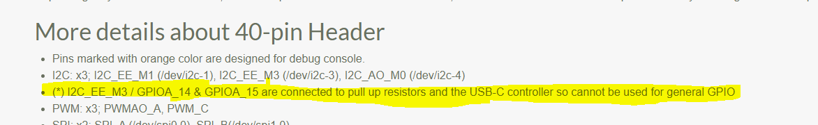
Hi there I m trying to use pins 3 and 5 for i2c communication similar to raspberry, however the bus is not activated. Already tried adding meson-g12a-i2c-ee-m3-gpioa-14-gpioa-15 to overlays in uEnv.txt file.
Tried both armbian and debian, doesn’t work.
I looked under /boot/dtbs/ and could not find the actual overlay. My kernel is 5.10.69-12-amlogic

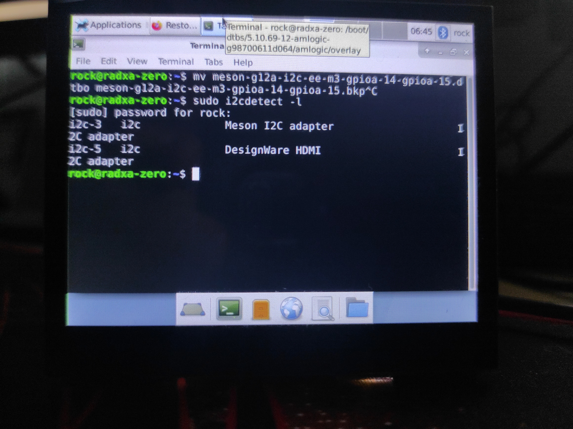
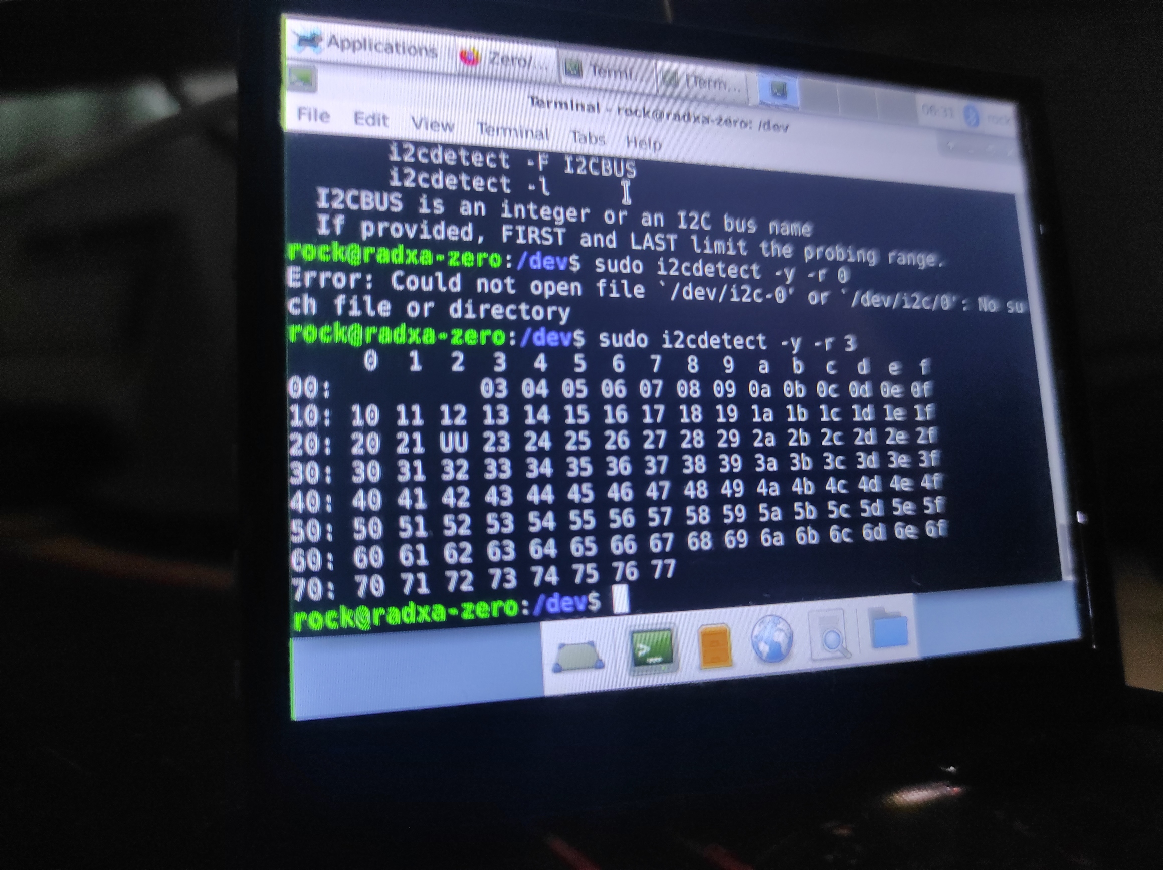
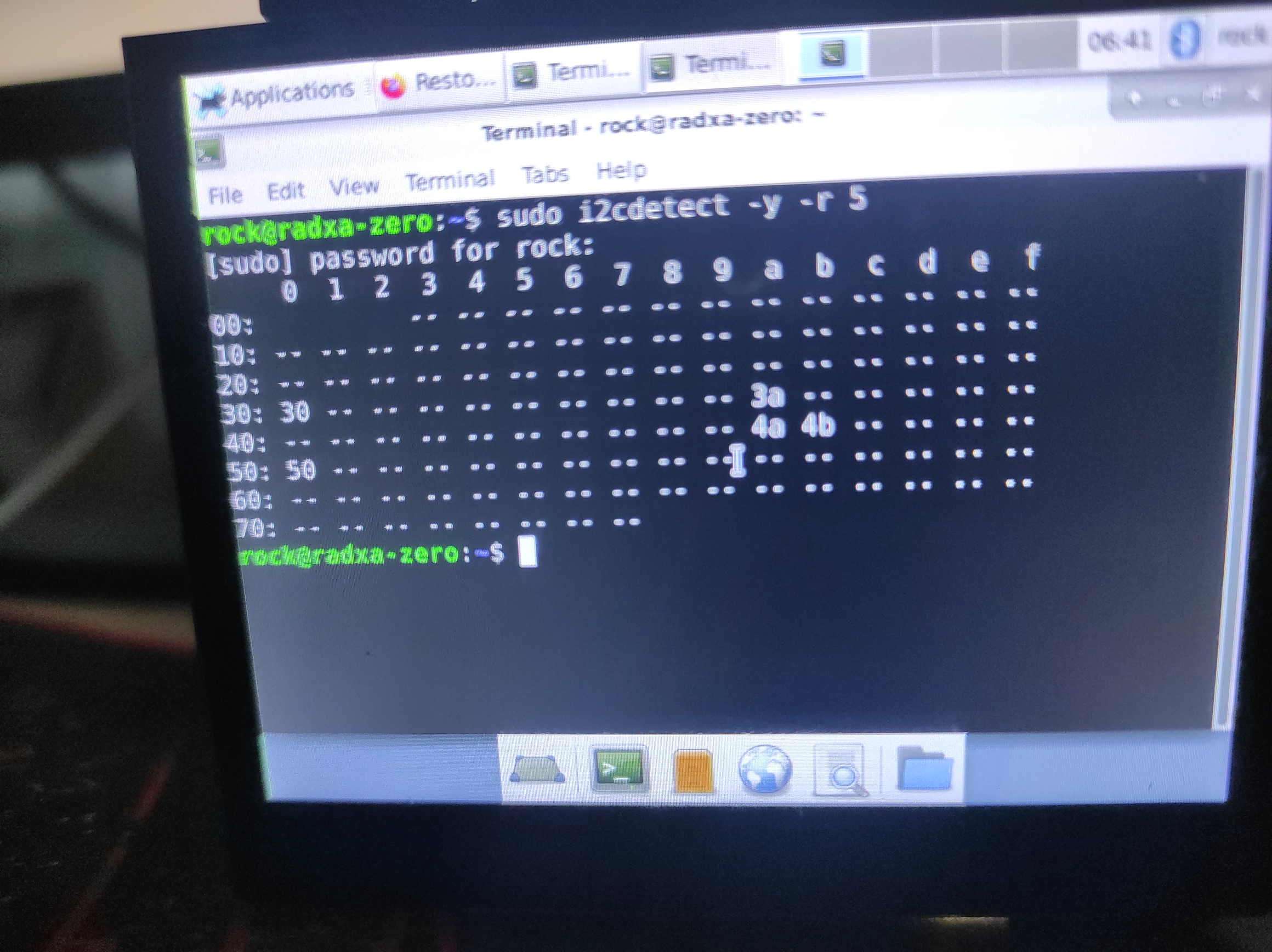
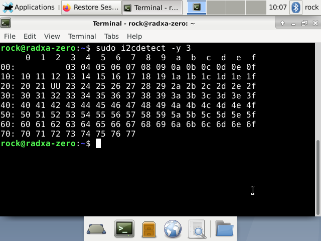
How can I activate the i2c bus on these 2 pins?

Sounds like you need to compile the meson-g12a-i2c-ee-m3-gpioa-14-gpioa-15 overlay and put it where your uEnv.txt can find it.

@teophile, do you have some links or a guide to compile the actual dtb? where would i get the source code?

Here’s the .dts for that particular overlay:

You should be able to compile it with sudo dtc -@ -I dts -O dtb -o meson-g12a-i2c-ee-m3-gpioa-14-gpioa-15.dtbo meson-g12a-i2c-ee-m3-gpioa-14-gpioa-15.dts

Then you move the resulting meson-g12a-i2c-ee-m3-gpioa-14-gpioa-15.dtbo to wherever other overlays are stored, usually somewhere in /boot. Then you can add the appropriate line in uEnv.txt or whatever boot script your system uses.

1 Like

I compiled and put the dtbo in /boot/dtbs directory, but nothing happened. Not sure why, uEnv.txt file has the overlay specified. It even says it is applying the dtbo overlay at startup Might try another distro as well cause I can t understand why it s not working.

What are you expecting to happen?

I was expecting for a new i2c bus to show up when I run i2cdetect -l or when i look into /dev/. Also I was expecting for touchscreen to start working since I was connected over those i2c pins to my 3.5 inch touch screen . Touch control works already over usb, I was trying to make it work over i2c.
Also the /boot/dtbs/5.10.69.12-amlogic-bla-bla/amlogic/overlays directory already had the file meson-g12a-i2c-ee-m3-gpioa-14-gpioa-15.dtbo. So it should have worked.

Okay, it sounds like you’re close. Can you post boot log (the output of whatever is saying the overlay is being applied) and dmesg?

Ok, I recorded the boot output since I could not find this output in logs. Please note the fact that the overlay meson-g12a-i2c-ee-m3-gpioa-14-gpioa-15.dtbo is actually applied: see https://www.youtube.com/watch?v=f9XTpn_XBuU

Then I dumped the output of journalctl -k -o short-precise -b -1 into a txt file(basically logs of last boot)and to wetransfer: https://we.tl/t-VSRJGTyIUA

I could not find anything unusual.

1 Like

Hmm, that is strange. You’re not seeing a /dev/i2c-3?

i have /dev/i2c-3 and /dev/i2c-5


but I m almost sure these are the default working buses, aka I2C_EE_M0 and I2C_EE_M1, I actually need I2C_EE_M3. Running sudo i2cdetect -y -r 3 gives the following :

and this is the output of sudo i2cdetect -y -r 5:

That overlay targets i2c-3 so that’s the device you’re looking for. i2c-5 goes to the HDMI interface.

I have two questions:

  1. Is it possible to remap the I2C interface I2C_EE_M3 from /dev/i2c3 to /dev/i2c1 in order to be compatible with Raspberry Pi software?

  2. What’s the device on that bus at address 0x20 showing up as UU?

  1. I don’t know about remapping, but you could try a symlink? It might be better though to configure or modify the software to use the appropriate i2c device.
  2. It’s the USB type-C controller.
1 Like

@theophile So regarding this i2c3 interface, specifically pins 3 and 5. It seems these cannot be used for GPIO as per the documentation. Do you know of a workaround to use these physical pins for i2c or there is no possibility? A lot of HATs on the market use these pins for communication, from displays to UPS es.

Those pins can be used for I2C. In fact, that’s all they can be used for. I’m using I2C over those pins in my project.

Screenshot_2023-02-14_10-07-26

This is what shows up when scanning the i2c3, pins 3 and 5. The rtc module addresses should show up since the module it’s connected to those pins. It shows like that even when I have nothing connected to these specific pins. How should I test it if it works on those pins since this is not helpful? Also why is it showing all these addresses as if it were in use?

Something is pulling pin 3 low. Check to make sure you don’t have SCL and SDA reversed. Also check with a multimeter with the power off and nothing connected to the board to make sure there isn’t continuity between pin 3 and ground.

Measuring the pins I get 0.06 V on pin 3 and 1.2 V on pin 5.

Also you were right, I detected continuity between pin 3 and ground. What can I do know?

If you have nothing at all connected to the board or to any of the gpio pins, you might have a bad board. You could check the traces and see if you can find the short.