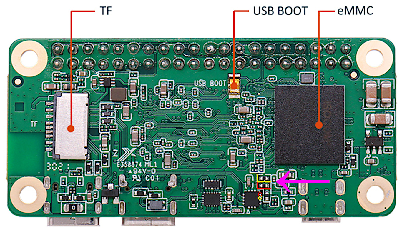
It just occurred to me that the USB-C controller is on that I2C bus. According to the schematic, the FUSB302 IC has 2.2k pullup resistors on both SDA/SCL lines, which should be sufficient to pull them high. Per the Radxa documentation, here are the locations of the pullup resistors and the corresponding pins on the FUSB302 IC. The red outline indicates the SDA line and the yellow indicates SCL.
With the board unpowered and nothing connected, one side of each resistor should have continuity with its like-colored pin. With the board powered up, the other side of each resistor should measure +3.3V.
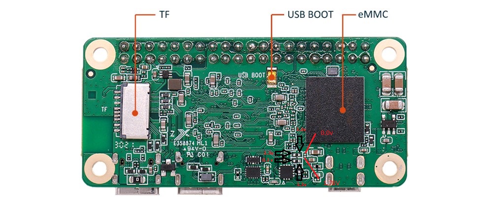
Another thing to check is the resistor that is at the lower-most prong of the pink arrow in the picture above. According to the diagram on the bottom of page 8 of the schematic, that’s supposed to be a 0-ohm resistor that connects board VCC to the VCC points in the FUSB302 circuit (with a 100nF decoupling capacitor). With the board powered on and nothing else connected, both sides of that resistor should measure +3.3V.
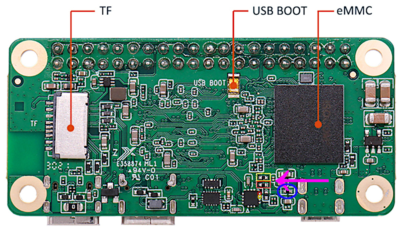
Sorry my earlier description wasn’t very good. The 0-ohm resistor is the one circled in blue:
But from your description it sounds like that’s probably not the problem anyway. If it were, you wouldn’t be getting +3.3V on the SCL line. Somewhere there is something pulling the SDA line low. If it were me, I’d get a microscope or magnifying glass and try to follow the trace all the way from the GPIO header to the SOC and see if there is anything amiss, like scratched solder mask or solder bridges. Check the underside of the GPIO pins too, just in case.
Another thing to check is make sure you don’t have any libraries or utilities running that might be pulling pin 3 low in software. As you noted, the Radxa wiki warns that GPIOA_14 and GPIO_15 can’t be used for general GPIO because the USB-C controller is on those lines, but that doesn’t necessarily mean that you can’t break it by trying to use those pins for general GPIO. One possible way to check this is to disconnect everything from the board and make sure it’s powered off, then connect the + lead from the multimeter to pin 3 and the - lead to ground. Obviously this will read 0 with the board powered off, but with the leads connected, power the board up and watch the meter. If it reads more than 1V at power-up, keep watching to see if it drops to close to 0 at some point in the boot process. If so, it’s likely a software problem.
Ok, measured the 0 ohm resistor circled in blue, it s fine, i m getting 3.3V on both sides, not the culprit as you already assumed.
- Looking through an electronic microscope I couldn’t find anything suspicious although I wouldn’t even know where to look at since I’m not electronist, just a software engineer hobbist.
- Testing the pin 3 with the board powered off, I don’t have continuity anymore between pin3 and ground. This is very odd, not sure why it changed, doublechecked, it’s gone.
- Measuring pin 3 while powering, the voltage rises only to 0.3 V and sits there.
Weird. Try i2cdetect again with nothing attached to the GPIO header. See if you get all addresses again. You should only get the USB controller at 0x22.