Flash SPI and SPL on Rock5B questions. (Caveat: SPL is never flashed.)

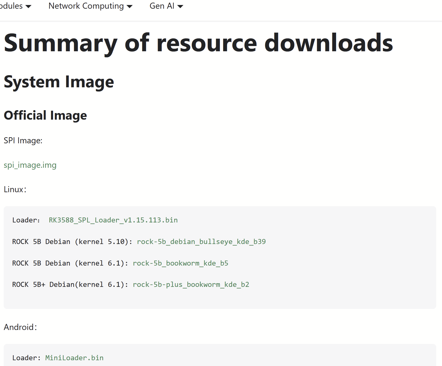
Hi, at https://docs.radxa.com/en/rock5/rock5b/download I see mentioned " Loader: RK3588_SPL_Loader_v1.15.113.bin".

Inside the directory view for this file rk3588_spl_loader_v1.15.113.bin at https://dl.radxa.com/rock5/sw/images/loader/rock-5b/release/ , I see that its date is recent - 2024-05-23. Definitely I have not installed this recent version.

In the same directory is a file “rock-5b-spi-image-gd1cf491-20240523.img”, with the same date 2024-05-23.

The clear and easy to understand installation instructions I find on the Wiki are for the SPI but not for the SPL: https://wiki.radxa.com/Rock5/install/spi#Simple_method

I see a mentioning of flashing the SPI and SPL file at the same time through the Maskrom mode via the USB port.

Can you please clarify, does the SPI flash file contain the SPL flash image too, so when I follow the “Simple method” SPI installation steps, the SPL is upgraded too?

Or, after going through the SPI installation steps which are from Linux running locally on the Rock5B, must I also shut down the Rock5B, connect it to another computer via MaskROM USB mode, and flash the SPI image separately via one of the tools prescribed? If you can detail this requirement and steps would be appreciated.

At the bottom of https://wiki.radxa.com/Rock5/install/spi I see a description that “RKDevTool” GUI is used on WIndows to flash the SPL file, then click “Erase all” and reboot.

Alternatively I see “rkdeveloptool db rk3588_spl_loader_v1.08.111.bin; rkdeveloptool wl 0 zero.img; rkdeveloptool rd” done in Linux - that must be Linux on a separate computer which is connected to the Rock5B in MaskROM mode via USB.

Do I need to go through these steps, or have I already updated the SPL implicitly as I asked above, or will just keeping an old SPL version be fine in all situations (boot via NVMe etc.)?

Many thanks

Digging a bit, I am told that the SPL is indeed separate from the SPI, and can only be flashed from another computer via USB MaskRom mode.

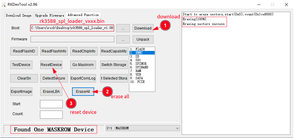
So the steps are as shown on this screenshot https://wiki.radxa.com/mw/images/c/c8/Eraseall_new.png :
First click the “Advanced function” tab.
Then specify the filename of the SPL loader file.
Then click “Download”.
Then click “EraseAll” and then click “ResetDevice”, and that’s all.

Did I get it right

An expert says “The spl loader is just a specially packed u-boot. I’m not familiar with the precise ins and outs of the downstream tooling and binaries, as I only use mainline stuff. “SPL” can mean both a stage of u-boot (so it would be part of your SPI flash’s u-boot) or it can also refer to the u-boot that gets loaded over USB into memory temporarily just to actually do any other operations on the board while flashing.”

Oh I got it, there was even more confusion.

So the way RockChip use the term “SPL”, it is only a transient boot code used specifically to kickstart the RK3588 during boot via USB MaskRom.

SPL is never a part of an RK3588’s normal boot process. It is only a MaskRom boot process thing.

Therefore, the SPL is not updated to a Rock5B board.

Meanwhile the “spi-image.bin” file advertised, is an u-boot distribution to be flashed to the Rock5B’s SPI flash chip.

Due to the above, I find it a bit confusing that the SPL version and filename is listed at https://docs.radxa.com/en/rock5/rock5b/download rather than the SPI. The SPI should be downloaded and flashed to have a recent UBoot onboard on the Rock5B especially to get NVMe boot support, while the SPL is a pure special purpose file, not used by normal users (aside from advanced mode SPI flashing via USB in MaskRom mode).

@RadxaYuntian What about on the Download page you show the SPI instead of the SPL file?

Thanks

Reading https://docs.radxa.com/en/rock5/rock5b/download one more time, I see now that the SPI file is linked above the SPL but the formatting is broken and a bit ocnfusing.

  1. wiki.radxa.com is no longer maintained. You should check docs.radxa.com instead.
  2. You only need to follow one of the following tutorial to install the system:

https://docs.radxa.com/en/rock5/rock5b/low-level-dev/maskrom

1 Like

I could not get precise info about those, any changelog or so,
for sure on some boards I managed to upgrade this firmware from 1.07 to 1.08, then first line on uart changes, right now its:

DDR Version V1.08 20220617

SPI has nothing to do about this, same thing pops out when SPI is missing. SPL seems to reside inside SoC itself.

As explained somewhere by a Radxa employee, SPL is just a loader that resides in RAM to enable the flashing process.

That would be 100% correct, but at same time I noticed that UART changes this particular line after some operation via maskroom and this survives clearing spi flash. It’s first boot phase so it’s nothing on sd or emmc (or nvme). That is why I assumed that there have to be additional firmware, maybe in soc itself or spi is not that blank as I expect (pi spi has area for eeprom).

Dor maskroom terminology is bit misleading. As far as I could understand loader is small program that can bootstrap and perform some operation such as connecting to pc via usb and downloading some image to sbc and specified area. Or just act as pendrive to allow using balena for same thing.

I need to recheck this with Rock 5A. There is no SPI there, but one is included for eMMC socket. I don’t remember right now how boot process looks like, but it should start UART output with blank sd card and then fail at second stage.

According to boogiepop in his rkddr project:

So it indeed starts with boot rom, so the question is - can we upgrade it? does that particular line comes from it or next stage? I noticed that some boards don’t start with no boot medium (no sd card) but did not double checked with completely empty card (new out of box).

Wait so the tertiary boot loader works before secondary boot loader? Whoever named these must not know what these words mean…

SPI is the comminication method in between SOC and flash chip. It has nothing to do SPL/TPL whatever.

Boot Process

SPI Flash is a 16MB flash in rock boards to have base bootloader.

To understand the full loading process you can refer to following picture:

First thing, bootcode/bootrom is inside the SOC, hardocded, readonly and can not be changed.

It boots to idblock at sector 0x40 hex, or decimal 64, or bytes = 64 * 512 = 32768 bytes

TPL & SPL are combined in single block called “idb / idblock / idloader” all same thing.

TPL is ddr_blob from rkbin, SPL is actually open source, and generated using u-boot.

So the reason why you have a small 16mb spi flash is, to have idblock and friends minimum in the device so that people wont have deal with this low level details.

So far the boot process is Bootrom -> TPL -> SPL

After that, it jumps to u-boot.img/itb, which is that actual u-boot. some times it is called “u-boot proper”.

After SPL boots to actual uboot at adress 0x4000, or 16384 decimal, or bytes 16384 * 512 = 8.388.608.

Sequence of Booting form different devices

Bootrom -> (search for a device 1) TPL -> SPL (search for a device 2) -> U-Boot (Search for a device3) -> kernel

At search for a device 1: bootrom searches only mmc devices (not even sdcards at some socs)
At search for a device 2: SPL searches mmc, and sometime sdcards
At search for a device 3: At this stage uboot initalizes all hardware, so it can jump to, sd card, mmc, nvme, usb, network boot nfs etc, everywhere.

Above chages from implementation to implemetation but thats the basic overall.

So in your 16MB tiny SPI device generally, there is Idblock(tpl/spl) + U-boot so that without much effort by default device can boot from anywhere.

Maskrom Mode

In maskrom mode, you dont need anything in any storage device.
Instead, your boot sequence is loaded to ram using USB based Maskrom protocol.

For this you need, minimum 2 binaries.
TPL: Same binary as in Previous TPL.
Loader: A modified U-boot SPL which can additionally handle the USB maskrom commands.

In past, Loader was also closed binary, but lately rockchip moved to u-boot based Loader and called it SPL_Loader.

PS: What i am referring as actual u-boot or u-boot propoer as the last stage is also composed of several components in a container called FIT format. This is where the ATF (arm trusted firmware) boot process happening but i am just skipping those to make things simpler.

2 Likes

Protip: You can use Xrock tool instead of rkdevelop whatever tool which is over complicated and hard to understand. Below tool is miles better.

1 Like

exactly what i thought when i first saw it. but kinda makes sense now, Tertiary -> Secondary -> Main (Primary). So it is in reverse, because They are all artifacts of u-boot, and they keep reducing the overall uboot to fit in bootlaoder size restirictions, first they came up with SPL then there was a need of TPL. So blame u-boot i guess.

1 Like

Ok, thanks for details,
Where memory training is done? On very first phase with boot rom or on next step?
When UART start to output anything? I’m trying now to connect UART logs with each phase,

sample output:

DDR 9fffbe1e78 cym 24/02/04-10:09:20,fwver: v1.16
LPDDR4X, 2112MHz
channel[0] BW=16 Col=10 Bk=8 CS0 Row=16 CS=1 Die BW=16 Size=1024MB
channel[1] BW=16 Col=10 Bk=8 CS0 Row=16 CS=1 Die BW=16 Size=1024MB
channel[2] BW=16 Col=10 Bk=8 CS0 Row=16 CS=1 Die BW=16 Size=1024MB
channel[3] BW=16 Col=10 Bk=8 CS0 Row=16 CS=1 Die BW=16 Size=1024MB
Manufacturer ID:0xff
CH0 RX Vref:30.1%, TX Vref:21.8%,0.0%
CH1 RX Vref:28.5%, TX Vref:22.8%,0.0%
CH2 RX Vref:30.1%, TX Vref:21.8%,0.0%
CH3 RX Vref:29.3%, TX Vref:20.8%,0.0%
change to F1: 528MHz
change to F2: 1068MHz
change to F3: 1560MHz
change to F0: 2112MHz
out
INFO:    Preloader serial: 2
NOTICE:  BL31: v2.3():v2.3-682-g4ca8a8422:derrick.huang, fwver: v1.45
NOTICE:  BL31: Built : 10:11:21, Dec 27 2023
INFO:    spec: 0x1
INFO:    code: 0x88
INFO:    ext 32k is not valid
INFO:    ddr: stride-en 4CH
INFO:    GICv3 without legacy support detected.
INFO:    ARM GICv3 driver initialized in EL3
INFO:    valid_cpu_msk=0xff bcore0_rst = 0x0, bcore1_rst = 0x0
INFO:    l3 cache partition cfg-0
INFO:    system boots from cpu-hwid-0
INFO:    disable memory repair
INFO:    idle_st=0x21fff, pd_st=0x11fff9, repair_st=0xfff70001
INFO:    dfs DDR fsp_params[0].freq_mhz= 2112MHz
INFO:    dfs DDR fsp_params[1].freq_mhz= 528MHz
INFO:    dfs DDR fsp_params[2].freq_mhz= 1068MHz
INFO:    dfs DDR fsp_params[3].freq_mhz= 1560MHz
INFO:    BL31: Initialising Exception Handling Framework
INFO:    BL31: Initializing runtime services
WARNING: No OPTEE provided by BL2 boot loader, Booting device without OPTEE initialization. SMC`s destined for OPTEE will return SMC_UNK
ERROR:   Error initializing runtime service opteed_fast
INFO:    BL31: Preparing for EL3 exit to normal world
INFO:    Entry point address = 0x200000
INFO:    SPSR = 0x3c9


U-Boot rknext-2017.09-33-f73b1ee-gaa35ac0 #runner (Aug 06 2024 - 08:45:28 +0000)

out indicate finished phase?

Certainly on last line u-boot kicks in.

Where memory training is done? On very first phase with boot rom or on next step?

in the ddrblob (TPL).

Below is TPL/SPL (i am not sure which one is which)

DDR 9fffbe1e78 cym 24/02/04-10:09:20,fwver: v1.16
LPDDR4X, 2112MHz
channel[0] BW=16 Col=10 Bk=8 CS0 Row=16 CS=1 Die BW=16 Size=1024MB
channel[1] BW=16 Col=10 Bk=8 CS0 Row=16 CS=1 Die BW=16 Size=1024MB
channel[2] BW=16 Col=10 Bk=8 CS0 Row=16 CS=1 Die BW=16 Size=1024MB
channel[3] BW=16 Col=10 Bk=8 CS0 Row=16 CS=1 Die BW=16 Size=1024MB
Manufacturer ID:0xff
CH0 RX Vref:30.1%, TX Vref:21.8%,0.0%
CH1 RX Vref:28.5%, TX Vref:22.8%,0.0%
CH2 RX Vref:30.1%, TX Vref:21.8%,0.0%
CH3 RX Vref:29.3%, TX Vref:20.8%,0.0%
change to F1: 528MHz
change to F2: 1068MHz
change to F3: 1560MHz
change to F0: 2112MHz
out

When UART start to output anything

ddrblob (TPL) configures UART, but i am not sure i spits anything.

out indicate finished phase?

most likely, i assume this is TPL speaking

Certainly on last line u-boot kicks in.

true

outputs of the first block can be further seperated if they are coming from TPL or SPL by checking the rockchip u-boot code, but i dont see much beenfit in doing so, i dont think SPL is doing something very useful than may be relocating anything is SRAM to DRAM, and may be extra mmc initialization

1 Like

So https://docs.radxa.com/en/rock5/rock5b is the official documentation page for the Rock5B now, good to know.

Perhaps you should add a note in the heading at https://wiki.radxa.com/Rock5 and all sub-pages, that the Wiki is obsolete and replaced by https://docs.radxa.com/en/ ?

It is great that you keep the wiki for archival purposes though.

About “rsetup”: I see on your documentation page that you have given your own Linux Debian etc. distributions the loose name “Radxa OS”.

This does not mean that you are making your own OS or Linux distribution, but instead it’s just normal Debian etc. and RadxaOS mostly means a script called “rsetup” https://docs.radxa.com/en/rock5/rock5b/radxa-os/rsetup , that you have made to help SPI and NVMe etc. flashing and configuring some other Radxa SBC specific functions in Debian?

About the distinction SPI vs SPL, please feel free to write a summary about which is which.

However, I see from your screenshot of “rsetup” that only SPI is mentioned, not SPL:


(https://docs.radxa.com/img/common/nvme/update_spi_bootloader.webp)

Meanwhile at your page that describes how to install via USB in Maskrom mode, that is under “low-level”-“Install OS via USB”-“Linux host” (https://docs.radxa.com/en/rock5/rock5b/low-level-dev/maskrom/linux), there only SPL is mentioned.

Previously in the installation instructions on your Wiki https://wiki.radxa.com/Rock5/install/spi#Simple_method , you recommended to go through the steps to clear the SPI flash before flashing it anew. Is this step baked into “rsetup” now or should one go through the clearing steps at https://docs.radxa.com/en/rock5/rock5b/low-level-dev/maskrom/erase separately?

Perhaps it would be a good idea to preserve the SPI flashing instructions from the Wiki (this: https://wiki.radxa.com/Rock5/install/spi#Simple_method )on your new docs page, and not just refer people to read “rsetup”'s sourcecode.

Finally I believe there is a typo here: https://docs.radxa.com/en/rock5/rock5b/getting-started/install-os/nvme says “Use the system utility rsetup to flush the SPI.”. What you mean is not “flush” (which means empty, wipe, sync) but “flash” or “upgrade”. The way it’s written right now, the advise to the user to upgrade the SPI flash chip to the latest version of u-boot is easily missed.

Many thanks.

1 Like

@Peter.Wang

There are more to it than vanilla Debian.

This is really low level and not something that matters to normal users. If you want to know more @boogiepop explained it above.

For now we are only focused on whether the documentation can be followed to perform those operations. It is not designed to be a programming reference.

Thanks for spotting it. I have created an issue for it.