Custom housing for RPi4 + SATA HAT

Hi everyone,

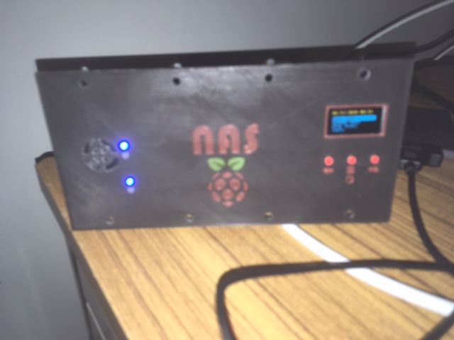
I’m making a custom rack housing for an RPi4 + SATA hat. Besides the ability to rackmount the setup I added an OLED display (128x64px) + 3 buttons for controlling display output and with the posibility to launch scripts (manual backup, show status, set IP, …)
Now I have a few questions on the available connector(s) on the HAT.

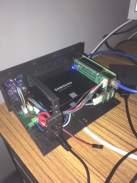
  1. I have version 1.2 of the HAT so with a barrel instead of USB power connector. Since I turn the setup 90° the HAT and RPi will be on their side with the barrel at the bottom (perfect fit for a 2U). However with the powerjack inserted underneath it becomes a bit a waste of space considering the rack mounting. Therefore I was thinking on using the ATX connector and mount a chassis at the back of the housing. 4-pin ATX has however 12V-GND-GND-5V. Is the 5V used on the HAT? Or is that a NC?
  2. The 10-pin PH-D connector has 2 GPIO (17+23), SCL, SDA, 3.3V, 5V, GND, GND, a NC and finally PWM (apparently connected to GPIO13)
    Questions here are:
    Can I connect my OLED to this connector or will it conflict with your software I had to install?
    What’s the use for the PWM? Is it for the optional fan? And thus again I probably won’t be able to use it when I have installed your software?

I have read on the forum there’s minimal installation available. Will this installation give me the liberty to use that connector for my setup?

  1. Last but not least. Included in my package was a small fan with 3-pin connector with rather short leads. Is it for cooling a certain part of the HAT (and if yes which part?) or is it to be directed onto the RPi processor? And if I do the minimal install will this fan still be correctly piloted?

Thanks for your time!

regards.

Forget about 1) I previously missed the NC next to ATX connector…:smirk: So only 12V is used.

1 Like
  1. check the pinout here:

https://wiki.radxa.com/Dual_Quad_SATA_HAT#PINOUT

avoid to use the gpio used already. For the OLED, if it’s the same driver, then you can just attach it to the same pins as ours.

  1. The 3p fan connector is for the pwm fan.

Thx for your time.

Ok so what is printed on the PCB next to the connector is not correct (5V and 3.3V are inversed)

I would prefer using different GPIO then yours, but the HAT covers the RPi free GPIO pins, so I’m limited to using the 3 GPIO available on the PH-D connector

The 3P fan connector is for the fan, agreed. But is there a certain part of the HAT board that needs cooling (hence the included FAN) or is it the idea to direct it at the RPi processor?
Also: If I install the lite version of your software, as mentioned on this forum, will that fan still be properly controlled? Or isn’t that part of the lite software version?

I also built a custom enclosure, and I use the lightweight install, so I figured I would chime in here.

You are correct that the 5v and 3.3v are printed incorrectly on the PCB, I also noticed that during my install.

The included fan is for the RPi CPU, no part of the HAT needs active cooling. With a properly ventilated case this fan is not needed, I use a passive heatsink on my RPi CPU with a PWM controlled case fan.

The lightweight script only gives support for the SATA connections (pins 22 and 37), it will not turn on the 3P fan or the top hat fan connected via pin 33.

Personally, I also use the 10 pin connector since the GPIO header is blocked. I used the lightweight install for the SATA connections and I have my own script that controls a case fan via PWM using pin 33. In the near future I plan to add an LCD screen and I will also break that out from the 10 pin.

EDIT: I am actually not sure about the 3P CPU fan since I never used it, it may not require any software control and therefore run correctly with any install, someone else will have to answer this.

Thx for the update.
Currently waiting for some parts to come over with China express, meanwhile I’m going to 3D print my case.
I’ll certainly come back with feedback on how it went.

Hi,

All items received, enclosure base printed and (almost) everything assembled.
Currently working on the code for controlling 2 fans.
My goal is to keep using the CPU fan as foreseen in the kit, replaced by a smaller one (due to space constraints in the housing) Next to that I made a PCB around a MAX6650 (i2c capable fan controller) to pilot an auxiliary fan with airflow on my disks.

If I look at the lite-script mentioned here above there’s no such thing as “fan controlling” included anymore, it basically turns the sata disks on/off. Period. (unless i’m missng something)

So I’m using the “full” code as a base for my project. My intend is to have 2 individual services. One for the fan controlling, one for the UI (buttons/display) I’m currently extracting the needed code for the CPU fan controlling where I stumble upon the fan.change_dc(). Am I correct to assume that the following line:
gpio.hardware_PWM(13, 25000, dc * 10000)
is used for PWM piloting of the Top-board FAN?
Which means cleaning up the things that include the GPIO13 would free-up that pin for another purpose.

As mentioned in OP I’m using 3 buttons on my UI therefore I need the 3 GPIO lines from the 10-pin connector leaving the sata-hat. That’s also why I chose to use a i2c fan controller so the disk fan is piloted over PWM ‘indirectly’.

Thx for the input.

EDIT: Am I also safe to assume that the other “hardware_PWM”:
gpio.hardware_PWM(12, 25000, dc * 10000)
pilots the CPU fan but you are not looking at the pwm pulses returned from the fan to actually regulate the speed?
If not so: where are the PWM pulses connected to?

EDIT2: @setq I was bumping my head against the wall this weekend analyzing the code for controlling the fan cpu as I couldn’t get it to work from my side. This morning tried another approach to figure out the details. Came to following conclusion: if you launch the “turn_off()” method from your fan.py the cpu fan goes to 100% speed, instead of the 0% you would expect. Is that correct? Do I need to understand the turn_off() more like: turn_of fan-control not necessarily turn of “fan” as such? If so I need to inverse my program’s logic.

EDIT3: Got it figured out. How strange the behavior might seem: It all depends on the PWM frequency I apply on the fan. Ideal frequency for the small CPU replacement fan seems 72.5kHz which is nowhere near the frequency the std software from radxa :slight_smile: (I wrote a small script which for a fix DC that changed the frequency in steps of, first 5kHz, then smaller steps once I had more an idea of the range) Then scanned the DC for that fixed frequency.) Easy peasy.
Also eliminated the OLED reset you do on GPIO23 as I don’t even have a RST pin on my display (freeing up another GPIO on the phd connector)
We’ll get there eventually :slight_smile:

1 Like

Almost finished.

DONE:

  • Custom housing design. Uses 4 units from this metal bracket (2U/19")
  • Designed auxiliary PCB for piloting disk fan around a MAX6650
  • Before mentioned PCB also receives the 10 PH-D connections from the HAT and forwards the i2c to a 128x64 OLED + 3 buttons. The PCB also receives 12V from a chassis mounted barrel and forwxards to the 12V input of the HAT
  • 4th button connected to RPi directly for cold start (after shutdown)
  • Reworked software from RADXA into multilayer menu for the OLED + buttons
  • Removed code to free up IO for the buttons
  • Tweaked PWM frequency for my new CPU fan (see previous post)
  • Created i2c library for the MAX6650

TODO:

  • Extend the config file to have different temperature levels for boths disks and CPU, and other options
  • Add the fan control for the auxiliary disk fan
  • Install Nextcloud
  • Add code to do a Nextcloud backup directly from the display
  • Add ‘Screensaver’
  • Add code to refresh host / system info automatically

Thought I’d upload some pictures about current status on the hardware.

First picture = the front (obviously)
On the left opening for airflow from my CPU fan.
Next to it the blue LEDs from the SATA hat from which the light has been brought to front by means of an acrylic tube
On the right the OLED display + main menu displaying
Underneath 3 buttons (left or up/menu or enter/right or down)
The red circle under the menu button gives access to a 4th, recessed button, hard connected to the Global_EN pin of the RPi (to boot the RPi after shutdown)

IMG_1758

Second picture = inside (even more obvious)
Front-left: support for a power switch and the barrel socket
PCB behind the support is for controlling the diskfan (not shown as it is mounted on the cover) over i2c via a MAX6650
In the middle 2 x 1TB SSD
On the far right: SATA hat and RPi4 / 4GB
Homemade multicolored PHD cable

Had some issues coding the screensaver, but all sorted now.
I will leave the code behind here once finished and after @setq approves as I use quite a bit from RADXA’s code.
I am however new to Python, so if you see at that point big nono’s or other/better means please bare with me and share so I can learn from it.

3 Likes