
At least I know how to create a asound.conf from scratch and was kind enough to share it.
Audio Support Rock Pi S
Oi, that’s so great, and totally justifies your disrespectful behaviour… no, it doesn’t.
1 Like
I did the update via apt… still only right channel is working.
also tried my second rock pi s - same issue. I will now start to build the kernel on my own.
1 Like
I really must have hit a nerve. Actually you are the person being disrespectful but hey, I understand you just can’t do any better. Now just calm down or go troll somewhere else…
Back to topic: would this be the correct place to get the kernel source? https://github.com/radxa/kernel/tree/stable-4.4-rockpis
Yes, that’s the right branch.
We have just tested audio on Rock Pi S. It works.
Update the kernel to version 4.4.143-27-rockchip, and using mplayer to play songs. Both sides of headphone have voice.
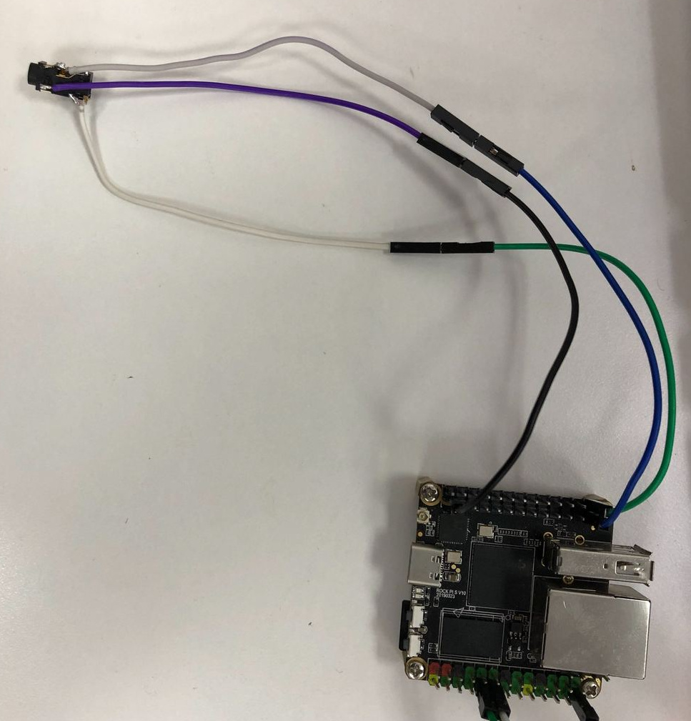
Hardware connection is shown below.
Three lines:
Blue — LINEOUT_R
green — LINEOUT_L
black — GND
2 Likes
Thanks for the picture! As there was a problem with one of the channels when I first tried to connect the headphone I forgot to recheck if I was still using the right pins. There was no explanation of the numbers anywhere. So DIYDealz was right at the end and I did connect the wires wrong 

I can confirm that both channels are working fine now! Thank you very much.
Congrats Stephen, to make it work! Would be cool to add a detailed wiring pic to the FAQ
@Radxa Team: Any thoughts about the multi-MIC setup?
Best regards
Mat
I am trying to get I2S output working, but need some help with the right device tree overlay.
For now, I enable i2s_8ch_xx for example, but not getting to far with this overlay:
// For ROCK Pi S
/dts-v1/;
/plugin/;

/ {
  model = "Radxa ROCK Pi S";
	compatible = "radxa,rockpis-rk3308", "rockchip,rk3308";

  fragment@0 {
    target = <&i2s_8ch_0>;
    __overlay__ {
      status = "okay";
      };
  };
};
Any pointers?
PS: I know there is no codec loaded, will tackle that at stage 2. 
This is the first of two messages in this thread - this one concerns the L and R Line Out. The second one will concern the Analog Microphone inputs.
My application for the Rock Pi S is audio for music. There is no other compact board with built-in multichannel audio inputs, and it is smaller than all the other boards anyway.
The L and R signals are on pins 26 and 25, the end ones furthest from the LEDs. A scope shows them to have the desired voltages, but no audio signals yet.
I followed the wiki instructions https://wiki.radxa.com/RockpiS/Debian, using the image file rockpis_debian_buster_minimal_arm64_191219_0406-gpt.img.gz :
rockchip-fstab           0.1
rockchip-overlay         2.2
linux-4.4-rockpis-latest 4.4.143-36-rockchip
rockpis-dtbo             4.4
and the xfce stuff. The basic installation already had two ALSA items:
libasound2:arm64   1.1.8-1  arm64   shared library for ALSA applications
libasound2-data    1.1.8-1    all   Configuration files and profiles for ALSA drivers
I installed the package jackd, which brought in jackd2 (there are at least two different implemenations of Jack, and this is the second one) and the GUI control program for it: qjackctl. There was still no aplay program, so I installed the alsa-utils package too.
The command aplay xyz.wav caused it to report playing the file via pulseaudio, but there were no output signals.
qjackctl > Connect shows no input or output ports.
aplay -l finds no soundcards.
aplay -L shows:
null
    Discard all samples (playback) or generate zero samples (capture)
jack
    JACK Audio Connection Kit
pulse
    PulseAudio Sound Server
default
    Playback/recording through the PulseAudio sound server
I also added the /etc/asound.conf file as described above:
pcm.!default {
        type hw
        card 1
}

ctl.!default {
        type hw
        card 1
}
I have no solid understanding of any of this stuff - I am just hoping to get aplay to actually drive the line out pins. Looking around in the machine, using the F3 view function of Midnight Commander to see the contents of some of these items in /proc/asound/ :
Loopback is a symlink to card0/. rockchiprk3308a is a symlink to card1/.
cards:
 0 [Loopback       ]: Loopback - Loopback
                      Loopback 1
 1 [rockchiprk3308a]: rockchip_rk3308 - rockchip,rk3308-acodec
                      rockchip,rk3308-acodec
devices:
  0: [ 0]   : control
 16: [ 0- 0]: digital audio playback
 17: [ 0- 1]: digital audio playback
 24: [ 0- 0]: digital audio capture
 25: [ 0- 1]: digital audio capture
 32: [ 1]   : control
 33:        : timer
 48: [ 1- 0]: digital audio playback
 56: [ 1- 0]: digital audio capture
pcm:
00-00: Loopback PCM : Loopback PCM : playback 8 : capture 8
00-01: Loopback PCM : Loopback PCM : playback 8 : capture 8
01-00: dailink-multicodecs rk3308-hifi-0 :  : playback 1 : capture 1
timers:
G0: system timer : 4000.000us (10000000 ticks)
G3: HR timer : 0.001us (1000000000 ticks)
P0-0-0: PCM playback 0-0-0 : SLAVE
P0-0-1: PCM capture 0-0-1 : SLAVE
P0-0-2: PCM playback 0-0-2 : SLAVE
P0-0-3: PCM capture 0-0-3 : SLAVE
P0-0-4: PCM playback 0-0-4 : SLAVE
P0-0-5: PCM capture 0-0-5 : SLAVE
P0-0-6: PCM playback 0-0-6 : SLAVE
P0-0-7: PCM capture 0-0-7 : SLAVE
P0-0-8: PCM playback 0-0-8 : SLAVE
P0-0-9: PCM capture 0-0-9 : SLAVE
P0-0-10: PCM playback 0-0-10 : SLAVE
P0-0-11: PCM capture 0-0-11 : SLAVE
P0-0-12: PCM playback 0-0-12 : SLAVE
P0-0-13: PCM capture 0-0-13 : SLAVE
P0-0-14: PCM playback 0-0-14 : SLAVE
P0-0-15: PCM capture 0-0-15 : SLAVE
P0-1-0: PCM playback 0-1-0 : SLAVE
P0-1-1: PCM capture 0-1-1 : SLAVE
P0-1-2: PCM playback 0-1-2 : SLAVE
P0-1-3: PCM capture 0-1-3 : SLAVE
P0-1-4: PCM playback 0-1-4 : SLAVE
P0-1-5: PCM capture 0-1-5 : SLAVE
P0-1-6: PCM playback 0-1-6 : SLAVE
P0-1-7: PCM capture 0-1-7 : SLAVE
P0-1-8: PCM playback 0-1-8 : SLAVE
P0-1-9: PCM capture 0-1-9 : SLAVE
P0-1-10: PCM playback 0-1-10 : SLAVE
P0-1-11: PCM capture 0-1-11 : SLAVE
P0-1-12: PCM playback 0-1-12 : SLAVE
P0-1-13: PCM capture 0-1-13 : SLAVE
P0-1-14: PCM playback 0-1-14 : SLAVE
P0-1-15: PCM capture 0-1-15 : SLAVE
P1-0-0: PCM playback 1-0-0 : SLAVE
P1-0-1: PCM capture 1-0-1 : SLAVE
version:
Advanced Linux Sound Architecture Driver Version k4.4.143-36-rockchip-g55b1ec35291f.
prc/asound/card1/id:
rockchiprk3308a
/proc/asound/card1/pcm0p/info
card: 1
device: 0
subdevice: 0
stream: PLAYBACK
id: dailink-multicodecs rk3308-hifi-0
name:
subname: subdevice #0
class: 0
subclass: 0
subdevices_count: 1
subdevices_avail: 1
I won’t list the full names or contents of the /proc/asound/card1/pcm0p/sub0/ and /proc/asound/card1/pcm0p/sub0/ items, but their hw_params, status and sw_params items are all “closed”.
In /dev/snd/ there are 9 items:
controlC0   symlinked from /dev/snd/by-path/platform-snd_aloop.0
controlC1   symlinked from /dev/snd/by-path/platform-acodec-sound
pcmC0D0c
pcmC0D0p
pcmC0D1c
pcmC0D1p
pcmC1D0c
pcmC1D0p
timer
I can dig up more details if someone points me where to look.
Does anyone have suggestions about how I can get line out working, and ideally have it appear to jack?
1 Like
This message concerns getting the analogue audio (microphone) inputs working.
The RK3308 TRM (Rev 1.1 Aug 2018, Part 1 https://wiki.radxa.com/RockpiS/hardware) page 144 onwards describes the audio codec. There is a huge amount of information here and I have only glanced at it. The datasheet (Rev 1.0 Feb 2018 at the same page) mentions on pages 12 & 13 that the DAC and ADCs are 16 or 24 bit, with sample rates between 8kHz and 192kHz. It remains to be seen what the signal to noise ratio of the ADCs is, considering potential problems with crosstalk on the PCB and imperfect isolation from the electrically noisy CPU parts of the RK3308 chip. Page 50 of the datasheet specifies 92 dB signal to noise ratio for the ADCs and 93 dB for the line and headphone outputs - which is perfectly good.
In addition to two inputs for each of the 8 microphone channels, there are also single inputs for CODEC_LINE1 and CODEC_LINE2 (datasheet) which are separate from the microphone inputs. However, I can’t find any other references to these, including in the diagram in part 1 of the TRM, page 145.
In the Rock Pi S V1.2 schematic, page 6, the balls for mic inputs 3 and 4 go nowhere. Page 19 shows the mic input signals for channels 1, 2, 5, 6, 7 and 8 going to connector J9102. On page 6 the signals for channels 1 and 2 are enclosed in a dash-line box labelled “Loopback”. However, I think this is spurious, since they seem only to be driven by J9102. So we have 6 dual input microphone CODEC inputs which drive high quality audio ADCs. This is an extraordinary resource to find on an ARM CPU.
The Firefly ROC-3308-CC schematics are at http://en.t-firefly.com/doc/download/53.html (Don’t use the Official option, since it lacks the proper file - the Google and MediaFire options have roc-rk3308-cc-v1_3.pdf). Page 16 show that the this board does nothing with the CODEC microphone inputs 3 through 7. The CODEC inputs for mics 1 and 2 are used (page 22) for monitoring the outputs of the L and R speaker amplifiers which are driven from Line Out. CODEC mic channel 7 is for a single microphone, also shown on page 22. The 32 pin connector for the mic array is all digital signals. So the Firefly board is no good at all for my application.
I had a look at the Firefly material (wiki) which is based on buildroot, not easy to use (for me) Debian boot images. On their forum there is some discussion of how to build kernels for the Firefly board to use these inputs. However, this is not for Debian . . . and it is in Chinese, so I would have to read it via Google Translate like this.
MicroZone’s MDK3308 Coreboard only seem to make the inputs for mic channels 1 to 6 available. This has only 256kB RAM, is bigger than the Rock Pi S and lacks the MicroSD card socket.
How can we use the 6 audio CODEC inputs of the Rock Pi S?
It was asked as to what users wanted to use with respect to audio inputs and outputs. I bought 2x Rock PI S because it has stereo analog audio out and at least one analog audio input.
EDIT: I’ve yet to try to get them working as I’m doing a few other things with the HW first.
Thanks!
Hi everybody,
I don’t know if this post could help someone out.
Here is how you can set up the I2S and PDM lines of the board so that you can use MEMs digital microphones, either by using I2S or PDM interface.
First of all, I installed on the SD card Radxa official ROM Ubuntu bionic (released on 19 Dec 2019).
Then I did updates and installed required packages for audio and set up
For updates
sudo apt-get update
sudo apt-get upgrade
For audio recording (I use SoX Ubuntu package)
sudo apt-get install libasound2 alsa-utils alsa-oss
sudo apt-get install sox -y
Then, in order to set up I2S/PDM pins on the board, you need to modify the device tree and recompile it. So you need to install the device tree compiler.
sudo apt-get install device-tree-compiler
Then go to /boot/dtbs/your_kernel_version/rockchip and decompile the device tree being used by the bootloader, that is rockpi-s-linux.dtb. To do so, you have to run
dtc -I dtb -O dts -f rockpi-s-linux.dtb -o rockpi-s-linux.dts
Once you have the dts file, open it and go to acodec-sound part
acodec-sound {
	compatible = "rockchip,multicodecs-card";
	rockchip,card-name = "rockchip,rk3308-acodec";
	rockchip,codec-hp-det;
	rockchip,mclk-fs = <0x100>;
	rockchip,cpu = <0xc3>;
	rockchip,codec = <0x8b>;
	phandle = <0x13d>;
};
You will have to change the cpu field. If you want to use up to 8 I2S microphones, you will have to change the value to <0xbe>, which is the phandle of the I2S0 controller (which is exposed on the pinouts layout). Remember you also need to enable the I2S0 interface, so go to i2s@ff300000 and change the status to “okay”.
i2s@ff300000 {
	compatible = "rockchip,rk3308-i2s-tdm";
	reg = <0x0 0xff300000 0x0 0x1000>;
	interrupts = <0x0 0x30 0x4>;
	clocks = <0x2 0x4c 0x2 0x4e 0x2 0xa4 0x2 0x6e 0x2 0x6f 0x2 0x3 0x2 0x4>;
	clock-names = "mclk_tx", "mclk_rx", "hclk", "mclk_tx_src", "mclk_rx_src", "mclk_root0", "mclk_root1";
	dmas = <0x25 0x0 0x25 0x1>;
	dma-names = "tx", "rx";
	resets = <0x2 0x89 0x2 0x8a>;
	reset-names = "tx-m", "rx-m";
	rockchip,cru = <0x2>;
	rockchip,grf = <0x4b>;
	rockchip,mclk-calibrate;
	pinctrl-names = "default";
	pinctrl-0 = <0x4e 0x4f 0x50 0x51 0x52 0x53 0x54 0x55 0x56 0x57 0x58 0x59 0x5a>;
	status = "okay";
	phandle = <0xbe>;
};
Once you have done all the changes, re-compile the dts file to get the binary format (dtb).
sudo dtc -I dts -O dtb -f rockpi-s-linux.dts -o rockpi-s-linux.dtb
Then reboot and enjoy!
In case you want to use PDM interface, just change the cpu field in the acodec-sound to <0xc3>, which is the phandle of the PDM controller. Then remember to enable the interface by changing its status to “okay”.
pdm@ff380000 {
	compatible = "rockchip,rk3308-pdm", "rockchip,pdm";
	reg = <0x0 0xff380000 0x0 0x1000>;
	clocks = <0x2 0x4b 0x2 0xa1>;
	clock-names = "pdm_clk", "pdm_hclk";
	dmas = <0x25 0xc>;
	dma-names = "rx";
	resets = <0x2 0x83>;
	reset-names = "pdm-m";
	pinctrl-names = "default";
	pinctrl-0 = <0x5f 0x60 0x61 0x62 0x63>;
	status = "okay";
	phandle = <0xc3>;
};
4 Likes
Hey ash,
check out my last post! Hope it helps.
Hey @baronets, Thanks for that, I am trying to get i2s output for an external DAC, but got a bit sidetracked, and haven’t yet managed. Here is dts I am playing with if your curious! 
Hi @ash. I have checked out your code.
I haven’t tried the armbian image, but if the DAC supports I2S protocol, it should work fine with the configuration I posted. What should change is the clock connection: in my case, I use RX clock. I assume you should only change it. In my case, it does not matter which microphone I am using, as long as both board and the transducer use the same interface.
Currently I am only dealing with multichannel audio recording  .
.
Hi @ash. I have checked out your code.
I haven’t tried the armbian image, but if the DAC supports I2S protocol, it should work fine with the configuration I posted. What should change is the clock connection: in my case, I use RX clock. I assume you should only change it. In my case, it does not matter which microphone I am using, as long as both board and the transducer use the same interface.
Currently I am only dealing with multichannel audio recording
Ah, maybe I understood this wrong, is the only way to access i2s via the acodec-sound node?
i.e I can’t define a different codec that directly uses the i2s@ff3x0000 interfaces?
I don’t have a scope right now to confirm if there are any outputs with my overlay, but I don’t see any mapping messages in the boot log such as with acodec-sound:
[1.242] rk3308-acodec ff560000.acodec: rk3308_codec_set_jack_detect: Request detect hp jack once
[1.244] rk-multicodecs acodec-sound: rk3308-hifi <-> ff320000.i2s mapping ok
Eitherway, I don’t think its a DAC/Codec issue, as the PCM5102a is as good as the dummy-codec, and should show up even when not connected.
But I am still a bit confused with the multichannel I2S outputs and mapping.
Looking at the i2s@ff300000 node in rk3308.dtsi
- Where are the enabled output/input pins defined? Is it
pinctrl-0?
– Are all 8i2s_8ch_0_sdiandi2s_8ch_0_sdopins active?
i2s_8ch_0: i2s@ff300000 {
	compatible = "rockchip,rk3308-i2s-tdm";
	reg = <0x0 0xff300000 0x0 0x1000>;
	interrupts = <GIC_SPI 48 IRQ_TYPE_LEVEL_HIGH>;
	clocks = <&cru SCLK_I2S0_8CH_TX>, <&cru SCLK_I2S0_8CH_RX>, <&cru HCLK_I2S0_8CH>,
		 <&cru SCLK_I2S0_8CH_TX_SRC>,
		 <&cru SCLK_I2S0_8CH_RX_SRC>,
		 <&cru PLL_VPLL0>,
		 <&cru PLL_VPLL1>;
	clock-names = "mclk_tx", "mclk_rx", "hclk",
		      "mclk_tx_src", "mclk_rx_src",
		      "mclk_root0", "mclk_root1";
	dmas = <&dmac1 0>, <&dmac1 1>;
	dma-names = "tx", "rx";
	resets = <&cru SRST_I2S0_8CH_TX_M>, <&cru SRST_I2S0_8CH_RX_M>;
	reset-names = "tx-m", "rx-m";
	rockchip,cru = <&cru>;
	rockchip,grf = <&grf>;
	rockchip,mclk-calibrate;
	pinctrl-names = "default";
	pinctrl-0 = <&i2s_8ch_0_sclktx
		     &i2s_8ch_0_sclkrx
		     &i2s_8ch_0_lrcktx
		     &i2s_8ch_0_lrckrx
		     &i2s_8ch_0_sdi0
		     &i2s_8ch_0_sdi1
		     &i2s_8ch_0_sdi2
		     &i2s_8ch_0_sdi3
		     &i2s_8ch_0_sdo0
		     &i2s_8ch_0_sdo1
		     &i2s_8ch_0_sdo2
		     &i2s_8ch_0_sdo3
		     &i2s_8ch_0_mclk>;
	status = "disabled";
};
Hi ash,
yes, pinctrl-0 tells you the pin configuration. I do not think you have to enable them, you only need to enable the i2s which controls them.
I think you could then simply use the acodec-sound, you need it to tell ALSA which audio peripheral to use when recording/playing.
I have not checked on this board, but when I set up in the same way another board (Nano Pi m4v2 by Friendly Elec), as soon as you start recording you have both tx and rx clocks working.
I have no experience with modifying the device tree with overlays, as my previous board was not supporting it
I am sorry if I am not technically correct, I learned everything by playing around with the board.
hi, i`m trying to get an analog microphone to work.
I connecetd it to pin23 (MICN1) and ground.
But it doesnt work. I`m using the ubuntu image.
I tried: arecord -d 10 -f cd -t wav --device=“hw:1,0” /tmp/test-mic.wav
to thest the microphone , but all i got is an .wav file with continuous buzzing.
Anybody got an analog microphone to work or can help me with that ? Thanks
1 Like
https://github.com/rockchip-linux/device-custom/tree/master/rk3308/rk3308_2mic_release-0.52-online
This chips benefit is not the number of mics that it can handle as without dsp aec/vad via the codec it becomes much less.
2 Mic would be brilliant as both Google and alexa have settled on this as an optimal cost/performance solution.
The multi mic beamforming setups still suffer vocode bleed degradation from crossover of singular predominant noise.
So in domestic situations where a loud TV or HiFi is playing and your trying to speak across actually they don’t work that great for recognition purpose.
They are amazing in more industrial dispersed noise where actor voice is predominant.
Are there any plans for 2 mic solution, maybe with pixel ring? As if it can use the binary blobs of vad and aec that seem to be already provided in the above repo then this becomes an extremely exciting product.
Currently the alternatives of Pi4 2gb and the Respeaker 4 mic USB comes with Aec. I haven’t actually tried the 4 mic linear for pi and can not work out if the loopback has aec dsp or not.
You can make a home assitant use something like https://mycroft.ai/ and as a singular unit it is exceptionally good, at a cost.
The problem Mycroft has is going back to domestic predominant singular noise sources that it can still suffer from extremely poor recognition if the actor voice isn’t predominant.
Like I say with beamforming you can have a high dispersed noise level and they work great but for domestic situations the same isn’t really true.
Unless the media source can be provided to the aec dsp loopback.
What mycroft and many builders need are low cost AEC/VAD wifi/bluetooth satelite speaker/mics that connect to a central RockPi4 or even X86.
It seems the major selling point of the RK3308 with built in dsp is being overlooked and wondering if you have anything in the pipeline?
Also do you have any working examples of some of the blobs Rockchip provide?
There is a big interest in opensource private non cloud AI where the load will likely be too high for the RK3308 but wow its a great low cost dsp audio networked satelite system to connect to a singular central unit (home ai cloud).