Hello
Could you help me, please? I want to make my built quieter.
From what I read above I’m ready to change the upper fan to Noctua NF-A4x10 PWM, also add the bottom fan (Noctua also?) connected by USB and weather strips for seal.
What is not clear to me:
Do I have to drill some holes in the bottom?
What is better to do with the CPU fan?
Which way should the fans run?
I will greatly appreciate any advice and guidance!
Thanks in advance)
Some experimentation will probably be needed. In my case I
replaced the top fan with a Noctua PWM fan. Mine blows out of the case. At the time I did this, blowing into the case made no difference for me. If I get really bored I may try reversing it again with the other changes I had made but I have no definite plans to change it at this time.
added weather stripping around the top board.
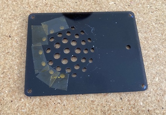
drilled the holes in the bottom plate to a larger diameter.
I removed the CPU fan entirely. It was noisy. Mine may have been broken from the start or I may have messed it up while moving things around. I don’t really know.
added an external 80mm fan that the whole unit sits on. Mine is a 12v case fan plugged into the USB port. Not all 12v fans will start and run on 5v. Mine does and it’s quiet, slow, but quiet. It also noticeably helps temps. It blows up, in theory, though and along the side of the case. If I switch the top fan I would probably switch this one too.
The things that made the most temperature difference for me were numbers 2, 4 and 5. I was surprised that removing the CPU fan made a big positive difference. Number 2 probably channels the air though where it is needed most. Number 1 and 4 probably make the most difference in noise level.
I may yet reverse the fans (again, I’m going to have to be really bored). I may also replace the heat sink on the CPU. I use the one that came with the unit with the fan removed. There are some large, possibly better quality, heat sinks out there. I may try one if I get the urge to take the unit apart again.
I did the airflow mod and ran some CPU benchmarks. My temps dropped by 10 °C when the CPU is under load! Just want to add my experience as a data point in the conversation.
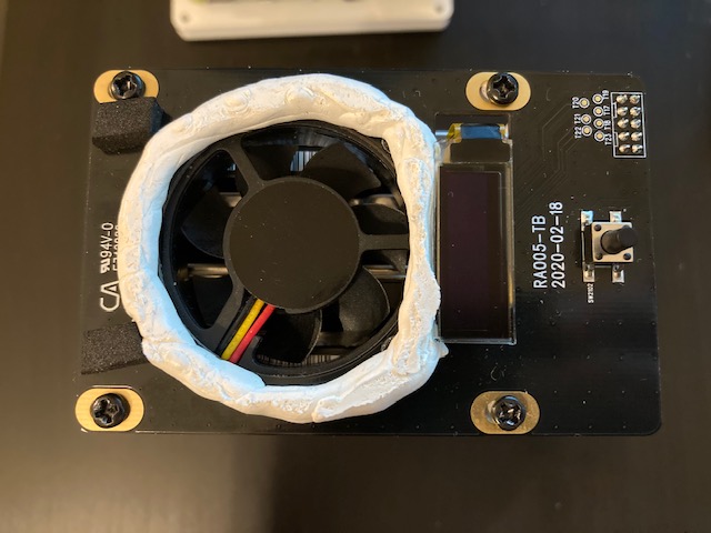
I used some sticky tack to improvise a gasket:
For context, I’m using a Raspberry Pi 4 Model B 8 GB. My top fan is sucking air out of the case.
I’ll share some details on how I ran CPU benchmarks. I used sysbench:
sudo apt-get install sysbench
Open two SSH sessions to the device. In the first session, run this:
sysbench --test=cpu --cpu-max-prime=200000 run
Wait for about 15 minutes for the temps to stabilize.
Then, run this command in the second SSH session for about 15 minutes:
while true; do cat /sys/class/hwmon/hwmon0/temp1_input >> example.log; sleep 1; done
Stop both processes. Run this to get the average temperature:
awk '{ total += $1; count++ } END { print total/count }' example.log
Additionally, you can get the hard drive temps with the following commands:
sudo apt-get install smartmontools
sudo smartctl -d sat -A /dev/sda | grep Temperature_Celsius | awk '{print $10}'
sudo smartctl -d sat -A /dev/sdb | grep Temperature_Celsius | awk '{print $10}'
sudo smartctl -d sat -A /dev/sdc | grep Temperature_Celsius | awk '{print $10}'
sudo smartctl -d sat -A /dev/sdd | grep Temperature_Celsius | awk '{print $10}'
There’s probably a shorter way of getting hard drive temps, but oh well.
Without the gasket, my temperatures were as follows:
CPU: 59.39 °C
HDDs: 41 °C
With the gasket:
CPU: 49.33 °C
HDDs: 38 °C
I recognize that this is benchmarking CPU load, not hard drive load, but still, I’m happy with the results.
I’m currently trying one more mod, which I’m not as sure about: covering the ventilation holes on the side with tape. Running the same benchmarks, I’m seeing a 1-3 °C drop with this mod:
CPU: 47.59 °C
HDDs: 38 °C
I know this seems counter-intuitive, so I’ll try to describe my thoughts behind this mod.
As I mentioned, my fan is in pull mode, i.e. it’s sucking hot air out of the case. I figure that with the side holes open, much of the air that gets sucked out of the case actually comes from the side. I’m guessing that a lot of that air just flows upwards along one of the hard drives, and out of the top.
Taping the side holes forces air to to be sucked into the case via the holes on the bottom. As such, almost all of the air coming into the case is forced to contact the RPi. Arguably, there’s more air flowing along the full length of the hard drives, too.
Anyway, I’m still experimenting with temperatures. Waiting for some parts to try a couple more things.
Edit #1: I tried removing the CPU fan, too. Here are the benchmarks:
CPU: 49.33 °C
HDDs: 37 °C
So for me at least, I lost a few degrees there. I could hear the top fan kick on at the 50 °C mark a few times, too, which wasn’t the case during my previous test.
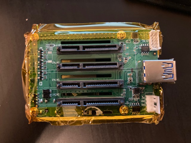
Edit #2: In the interest of experimentation, I tried adding a “skirt” of polyamide tape (Kapton) around the SATA PCB:
(The top “gasket” of sticky tack is still there, and the CPU fan is still removed.)
My idea was that this skirt could serve as a gasket, forcing air to be drawn through the slots in the SATA PCB, visible in the photo above. As the air was drawn through the slots, it would pass over the CPU heatsink. I figured that the cooling effect in this configuration might be more than if the air was allowed to pass on the outside of the SATA PCB.
To reinforce this effect, I taped the top row of the three rows of holes on the side. The top row of holes is above the SATA PCB, but the bottom two rows are below it.
Unfortunately, the benchmarks weren’t great:
CPU: 49.89 °C
HDDs: 38 °C
I taped the bottom two rows of holes on the side, and ran the benchmarks again:
CPU: 49.79 °C
HDDs: 38 °C
Not great. These tests make me wonder if maybe what’s happening is that the CPU fan blows air on the CPU, which gets pushed outward, towards the edge of the enclosure. The enclosure then absorbs some of that heat, and then, the fan on the top hat sucks the hot air upwards. Whether the hot air travels up through the middle or along the sides doesn’t matter as long as it gets sucked out.
I know that all of this testing is pretty crude, but I thought I’d share my results, even if they weren’t positive. Maybe this will save someone some time, if they get the same idea!
First, I discovered that my stress-testing method is suboptimal. The sysbench command that I was using was only pegging one of the four cores to 100%.
Here’s the new command I’m using to stress test, which pegs all four cores to 100%:
sudo apt-get install stress
stress --cpu 4
Otherwise, I kept the same test procedure as before:
Start a stress test
Wait at least 20 minutes
Measure for at least 20 minutes
Average the measurements
I decided that measuring hard drive temperatures for these tests is irrelevant.
I decided to use the following mods as a baseline for further experiments:
Use sticky tack to make a gasket at the top
Cover the side holes with tape
Additionally, I covered the following holes in the top hat with tape on the inside, since they allowed air to flow outside the gasket:
I ran a multi-core stress test against this baseline setup. The difference is dramatic:
Single-core: 47.59 °C
Multi-core: 56.85 °C
That’s a huge difference! Remember that the test I did earlier for an unmodded case showed 59.39 °C when stressing a single core. I think it’s reasonable to assume that we’d see temperatures above 60 °C if we were to stress-test all four cores. However, I don’t feel like undoing all of the mods I’ve done (which I’ll get into momentarily) just to see how big of a temperature improvement they’ve made.
With the baseline recorded, I made some big changes.
First, I made some changes to my /boot/config.txt:
# Reduce idle frequency, avg. 400 (default 600, avg. 700)
arm_freq_min=200

# Enables dynamic voltage
# https://www.raspberrypi.org/forums/viewtopic.php?f=29&t=257394
dvfs=1

# Undervolt to reduce temps, can only go one step
# This results in 0.8350V (default 0.8600V)
over_voltage=-1
I don’t think the dvfs directive actually does anything in this instance. Reducing arm_freq_min should lower idle temperatures a little. I ran a stress test after undervolting, and got 55.47 °C for a gain of 1.38 °C. Not much to write home above, but I’m keeping it, so that’s our new baseline.
Next, I got a new heatsink:
I bought the Geekworm Raspberry Pi 4 11mm Embedded Heatsink (P165-B). I bought both the P165-A and the P165-B. The P165-A is a piece of crap. There are some reviews which say that the heatsink don’t contact the components correctly. I can say from trying both heatsinks that those reviews are referring to the P165-A. The P165-B is almost perfect, however. You must use thermal paste, not thermal pads. Otherwise, it fits my RPi 4B perfectly.
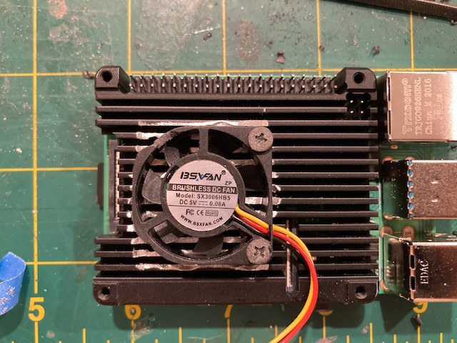
I decided to reuse the fan that came with the SATA case. I had to file down some of the plastic casing on the fan so that it wouldn’t collide with the power jack and the 1R5 inductor (?) on the SATA HAT. You can see the notch I filed for the inductor in the photo below.
Additionally, in order to get the fan to fit into the heatsink, I had to remove about 1.3-1.5mm of aluminum from where the fan sat on the heatsink. This was a big pain. I used a drill press with a 1/4" bit to carefully remove some material from the heatsink, and then, some files to finish the job. I would absolutely not recommend doing that. A rotary tool would have worked better, but I didn’t have one on hand, and I wanted it done ASAP.
This heatsink is tapped for M3 screws, but the screws provided with the default heatsink for the SATA HAT are M2.5. I had some nylon M3 screws on hand, so I sanded their heads down, so that they wouldn’t collide with the component leads sticking out of the SATA HAT PCB.
With the new heatsink, my quad-core stress test resulted in 49.29 °C for a gain of 6.18 °C versus the undervolted baseline of 55.47 °C.
I decided to take it one step further and reverse the fans. This fan now blows air onto the CPU:
I had to make a new notch for the 1R5 component, and I had to make some new screws for this setup. The heads on the M3 screws were too wide. I stuck a standoff into a drill, screwed a 20 mm nylon screw into it, and held some 100 grit sandpaper to the screw while letting the drill do its thing. I used some side-cutters to shorten the screws to about 9.5-10mm.
Lastly, I removed the tape that was covering the holes on the side, and I flipped the fan on the top hat around so that it sucked air into the case, instead of blowing it out:
I used some 20 mm nylon M3 screws here, too, and snipped them to the correct length. Tentatively, having the top fan in this orientation makes it less noisy, even at the same speed. Sucking the air through the holes makes less noise than blowing air through them?
With that done, my final results are as follows:
Quad-core stress test: 48.02 °C
Idle: 44.52 °C
I ran that stress test for 2.7 hours, and in that time, it peaked above 50 °C for only one second!
Unfortunately, my idle temps do peak above 45 °C periodically, every few minutes or so.
I’m going to tinker with the top fan speed so that it doesn’t jump from 50% at 40 °C to 75% at 45 °C. Maybe having a smoother transition instead of a sharp jump, or even just having it run at like 55-60% at 40 °C will keep the temps from hitting 45 °C.
I’m also going to put the hard drives to sleep after a period of inactivity, using hdparm:
Lastly, I did order the 4-pin PWM 5V NF-A4x10 Noctua fan for the top hat. It should be coming in this week. Will be interesting to see how it affects temps.
I recognize this is probably obsessive at this point, but it’s been a lot of fun figuring out how to optimize this thing. I ordered this product knowing that I was going to tinker and hack with it, and it has definitely delivered in that regard so far.
Hahaha, really great job. I ordered the same heatsink and planned to post some benchmarks here as well. But well, you were faster . Very entertaining to read though and I’m curious what the noctua fan will bring. I might still post some benchmark of my final result since I’m also tinkering around to get the coolest SATA hat. And maybe the race for the coolest sata hat is not over yet ^^
Haha thank you! I’m glad someone’s enjoying my write-up. Please do share benchmarks, if you decide to do the mod yourself. I definitely suggest using a Dremel to shape the heatsink—not a drill press or hand files.
So… the (first) NF-A4x10 that I ordered from Newegg got handed off from UPS to USPS. It was supposed to arrive over a week ago, but it’s still showing up as stuck in the handoff in USPS’s tracking system. So I said screw it, and ordered another one from Amazon, and what do you know, it got here the next day. I can see why Amazon makes the big bucks.
I installed the NF-A4x10 today. It’s going to take me a bit to run all the benchmarks I want to try, but I want to share my fan swap process. I think I did a pretty clean job, and I took some measurements that others might find useful.
First, I ordered this set of JST 2.0 PH-3 connectors. I have at least 18 left. I don’t know if this is allowed per the forum rules, but if you (person reading this post) live in the USA, and if you would like some of these connectors, feel free to send me a PM, and I’ll throw three of them in an envelope and send them your way for free. I have no use for them. Just know that USPS is slow right now.
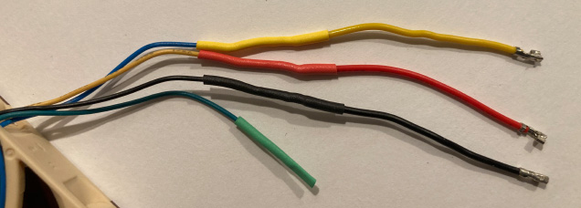
(Note that the red-black-yellow wire order on these is not the same as on the original fan.)
Next, I cleaned up the fan wires. I removed the connector housing, cut off crimped leads, and removed the heatshrink and paracord. I needed to figure out where to connect the wires from the pre-crimped connectors to the wires from the fan. To do so, I measured the length of the wires as they would lie in situ, with the fan in both orientations. I wanted to ensure that the connection wasn’t in a place where the wires would need to bend.
I found that the optimal length was about 95 mm total, with the wires leading from the fan and from the connectors cut at the 55 mm mark, and then, stripped back about 12-13 mm. Here’s a rough illustration:
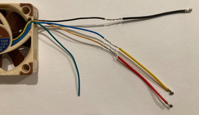
Next, I cut, stripped, and spliced the wires together with solder. Here’s a little in-progress photo:
Finally, I added some heatshrink, which was 1/16" diameter and about 1" long:
Warning: Put the heatshrink pieces on the wires first, before splicing them together! I thought I could get away without doing it because the connectors were so small, but I was wrong. I had to (mostly) bend down the little metal tabs on the connectors, which keep them in the housing. After inserting the heatshrink, I used a razor blade to carefully lift them back up.
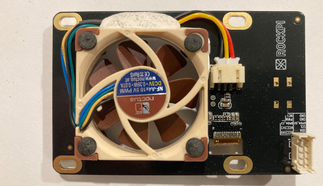
Here’s how it looks like once attached:
I used some more sticky tack to ensure that the wires stay in place. I also added a thin “grout” of sticky tack along the outside of the fan (visible on the right side of the fan in the photo above) to ensure that no air got sucked out from the case.
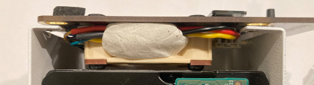
Lastly, you might have noticed in the photo above that I had to modify some nylon M3 screws, yet again, which seems to be the theme of this project! The screws I have (standard Amazon issue) have heads that are too tall for the case. They collide with the hard drives, and push the fan PCB up like so:
Shaving them down to somewhere below 1 mm fixed that issue. I sanded away the screw driver slot, but I didn’t have a problem hand-tightening them without one. I don’t think you’re really supposed to tighten them all that much in this instance: if you make them too tight, you’d just be squashing the anti-vibration pads.
I ran a couple benchmarks with the new fan. First, I found out that it idles at a temperature that’s pretty much identical to the original fan:
Original fan: 44.52 °C
NF-A4x10: 44.35 °C
Just for fun, I set both the top fan and the CPU fans to 100%, which resulted in an idle temperature somewhere around 39 °C. So that’s pretty good, but way too loud for idling.
Going off of that, I’m reframing my goal: I want to aim not for the coldest idle temperatures, but rather for the quietest idle operation, while keeping temperatures reasonably low. Previously, I was aiming to idle below 45 °C, but now, I’m fine with with aiming for 50 °C if that means quieter operation.
With that in mind, I’m trying something new: I’m setting the fan to a constant speed, and letting it run idle for a while to see at what temperature it stabilizes. I’ll also use an app on my phone to measure the noise level about 1" away from the side holes near the bottom (exhaust) and from the top fan (intake).
So far, I’ve only done one test. I’ve set the fan speed at 50%, and it stabilized at 48.16 °C. I ran it for 3.1 hours, and in that time it peaked above 50 °C for 8 seconds. The average noise 48 dBA at exhaust and 43 dBA at intake.
That’s it for now! I’ll report back after I’ve tried a few more things.
@jikky1800 as long as its kept below the height of the USB ports / Ethernet port, it will work… but, the clearance between the top of the sink to the bottom of the hat is maybe 3-4mm?
i’m planning to rewire it to power it off the hat’s fan connector… just ordered it, waiting for it to arrive…
so… after suffering from CPU fan failure (the quality of the fan is bad, seriously), i sought out replacement fans or heatsink for the raspi (on top of the noctua 40mm fan replacement for the top hat) as i stay in the bloody hot and humid tropics and my daily temps hover around 34 deg, which is HOT…
these are the two solutions i tried:
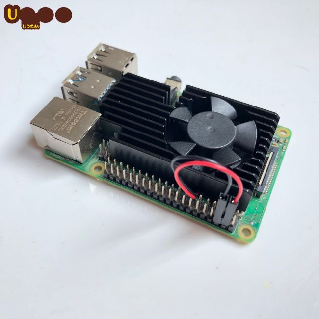
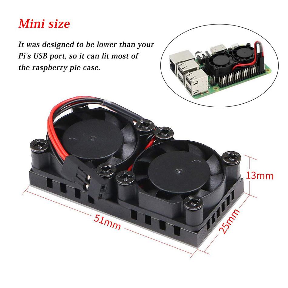
1. mini dual fan heatsink.
Had to jank the connecters a little for it to work with the sata hat, nothing major. The temps were disappointing as the pi is idling at about 51 deg (on a cooler day) to 54 deg (on a hot day)… and it goes up as high as 60+ on load (ie, mdadm raid array check)… highly not recommend this heatsink… the fan dies very fast too… mine died in like 3months…
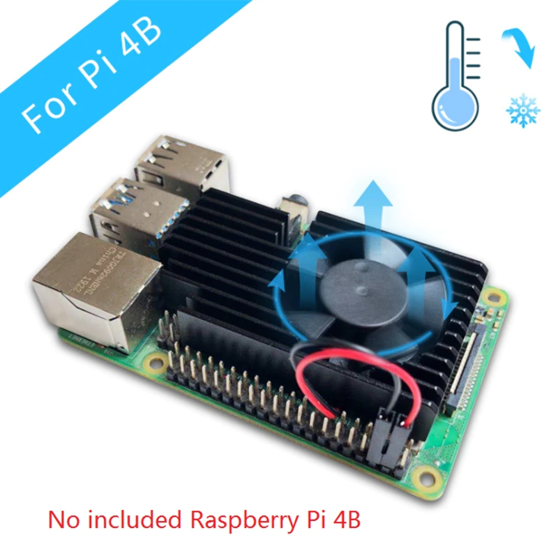
2. Aluminum heatsink with integrated 3510 fan
Same thing, had to jank the connector to work with the sata hat, but no big deal… make sure you buy the correct version for the 4B as there is a version of 3 that will not work due to the LAN port in the way… the fan is a standard 3510 fan, and you can get replacements from aliexpress (though its hard to find for some reason)… Temps wise this is the best… idle temps are below 45 consistently, dipping down to 40 on cooler days and going up to 51 on load… i would definitely recommend this heatsink…
After struggling with heat issues with the Quad Sata Hat Kit over the past 2 years, which resulted in USB disconnects and R/W errors each time (uptime was measured in days only), I’ve finally managed to solve it by moving the setup to a more traditional NAS Enclosure similar to the one depicted in the link.
To use the RPi with a Mini ITX power supply, a power bypass button must be installed. I found some ready made ones for sale online.
I cut out a ~7" x ~7" thin plywood which is similar to the ITX motherboard footprint, and placed the RPi + SATA Hat + Base plate in the empty space for the ITX motherboard vertically. THe plywood board was used to hold the RPi + SATA Hat in place. (I thought I would need to mount the RPi on the plywood board, and then secure the plywood to the ITX motherboard screw holes, but it turned out that there was enough support from the coiled SATA cables to hold it in place like a spring.
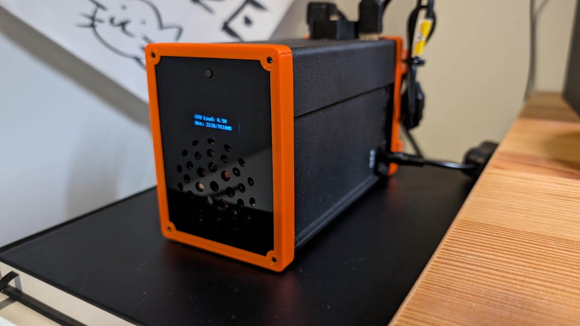
The drawback of my setup is that I cannot easily determine the operational status of the RPi, since the power indicators will still be on after a shutdown. I disconnected the top hat OLED display since it no longer works, probably due to overheating.
The only issue has to do with the connection from the SATA Hat to the NAS backplane. The SATA headers are female on the SATA Hat, while the NAS backplane uses the 7-pin male SATA connectors that are commonly found on ITX motherboards.
I had to hack some 7-pin Male-to-Female SATA extension cables to plug them into the SATA Hat, since the hat was designed to mate directly with 2.5" SATA HDDs using fused SATA+Power connectors. So far, after one week of operation it still seems to be fine (no USB / SATA disconnects or R/W errors) despite my fears of the connectors coming loose due to heat expansion.
Not sure if there are other SATA extension cables which could be used instead of the hacky solution I came up with.
For future users: Given that I live in a hotter country, I had to do something about the temperature in my setup… it was running in the mid 50s (Celsius) when idle…
the basics:
SATA Quad Hat with
Raspberry Pie 4B
3x SSD connected
Winter/Spring time was blissful and everything ran cool-ish… Summer temperatures started to rise, so did the CPU temperatures…
I followed some advice from here and further added some more mods:
Reversed the stock CPU fan to blow onto the heatsink (needed other screws)
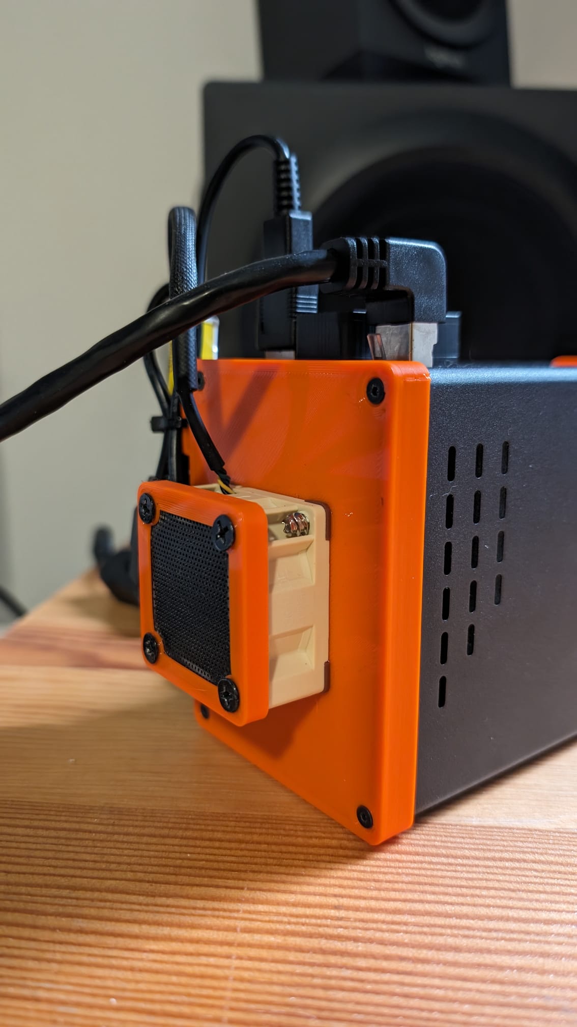
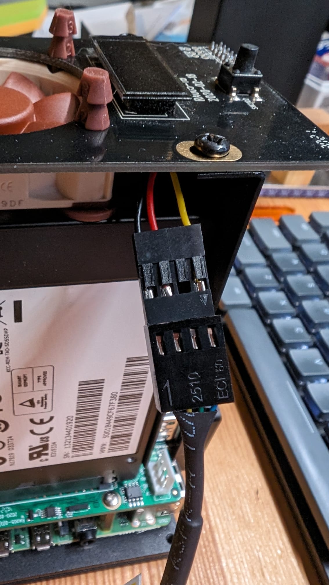
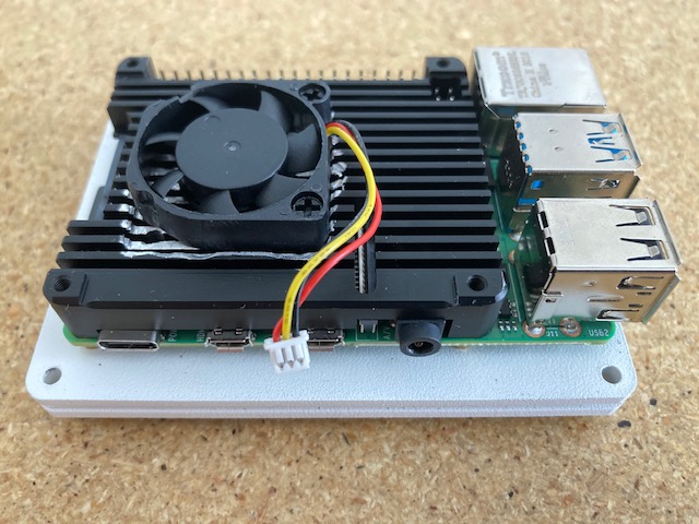
changed the top fan for a Noctua 4pin PWM fan, rewired the existing(see pics) - also blowing to the inside. cable is just sliding down on the side
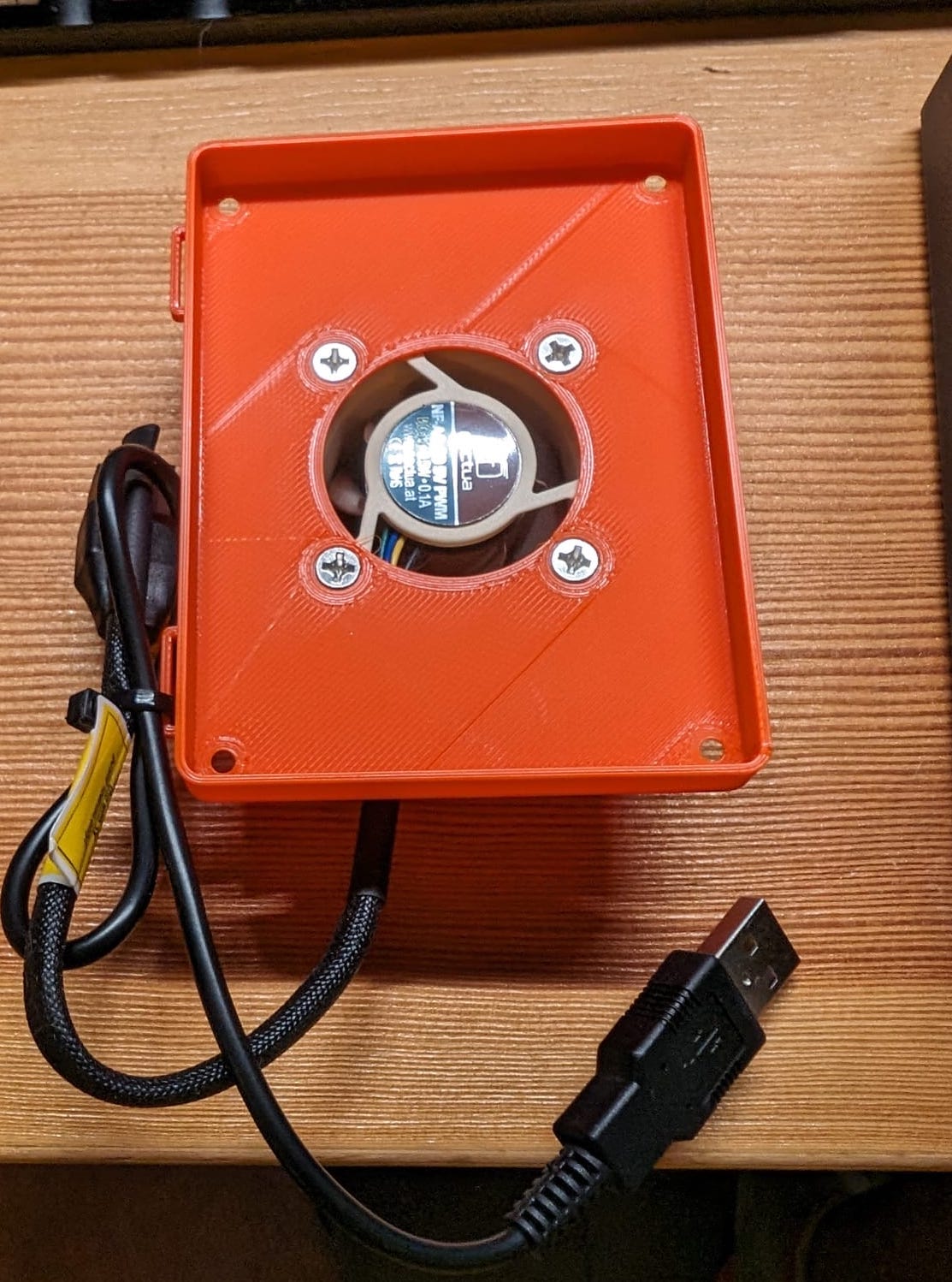
added a USB fan on the bottom (blowing into the case) with a 3D printed cover to force the air through the enclosure and block the side escape route (see pic)
3.a the cover has loops to zip-tie the cabels as needed
added a dust filter (catching dust and cat hair )
it is now standing on the side with rubber feet attached and running very quiet
20 minute stress test on the CPU: without the bottom fan constant 70C (I think the Raspberry starts throttling to keep the temp). with the bottom fan it hovers around 60C… so, very happy with the result!
Thanks for reporting that,
For my setup simple radiator + turbine fan on outside did the trick, whole case is metal and this one helps to reduce temperature inside. It’s not perfect fix but helped
Have You used 10mm or 20mm noctua fans? FLX version may be better option here,
If You have only ssd drives inside - than just check Your model via Internet, most of those are way smaller than standard 2.5 inch drive, so You will get much more space inside (and much bigger/quiet fan).
on the bottom, I installed a 20mm fan, for the higher air circulation (and it was the same price as the 10mm fan). For now, I wanna try to connect the bottom fan to the top fan, so they both get regulated by the temperature program of the top hat… Or, alternatively, install the a flx-like solution (resistor cable)…
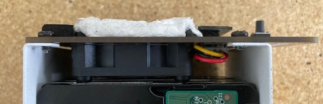
As you can see in one of the pictures, the Noctua fan touches the top of the SSD drives, as the rubber inlays in combination with the rubber “screws” made them a bit thicker… Maybe in the future…

 . Very entertaining to read though and I’m curious what the noctua fan will bring. I might still post some benchmark of my final result since I’m also tinkering around to get the coolest SATA hat. And maybe the race for the coolest sata hat is not over yet ^^
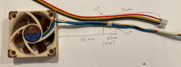
 )
)