
Hey all, first post here! Trying to get a Radxa 3W hooked up to an SSD1351 based OLED display via SPI.
Running the default image / OS, and the Radxa provided libmraa that I built on the device. I have a piece of software written in C++ that works fine on a Raspberry Pi Zero (albeit wired differently for that device’s GPIO pinout).
I have enabled the SPI overlay, and run my software to find the screen not working.
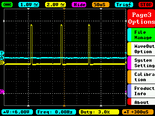
I tested the SPI lines with an oscilloscope and found two observations:
-
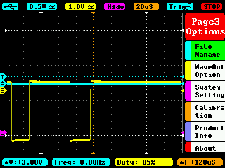
The SPI clock line appears on a different pin than the documentation. I find pin 23 (SPI3_CLK_M1) is always low, but pin 24 (SPI3_CS0_M1) shows a clock signal when my software runs. Why is this??
-
The SPI MOSI data line appears to be pulled high (or low?) and shows a sawtooth waveform. Does it need a resistor to ground somewhere? Is there a software-only fix for this changing the internal SPI / GPIO pull-up or down setting?
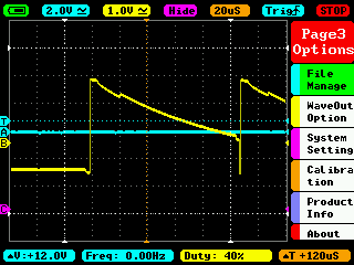
Edit: Added a 1k resistor to ground and it cleaned up the MOSI line. Display still doesn’t want to work though.
Any help would be appreciated. Thank you.