
Yes, but it should be just similar to what was in the repo.
Working SPI Display
I am also not the best person to teach you about device tree overlays. The guide is just fairly a working demo that was based on the original guide that I found. It was fairly translated to english since it was originally in Chinese.
Also, I stopped poking around this board due to very limited support. And as expected, if you want to make things work you might be required to have some good level of understanding just like some of the people who are still dedicated to work on this board.
1 Like
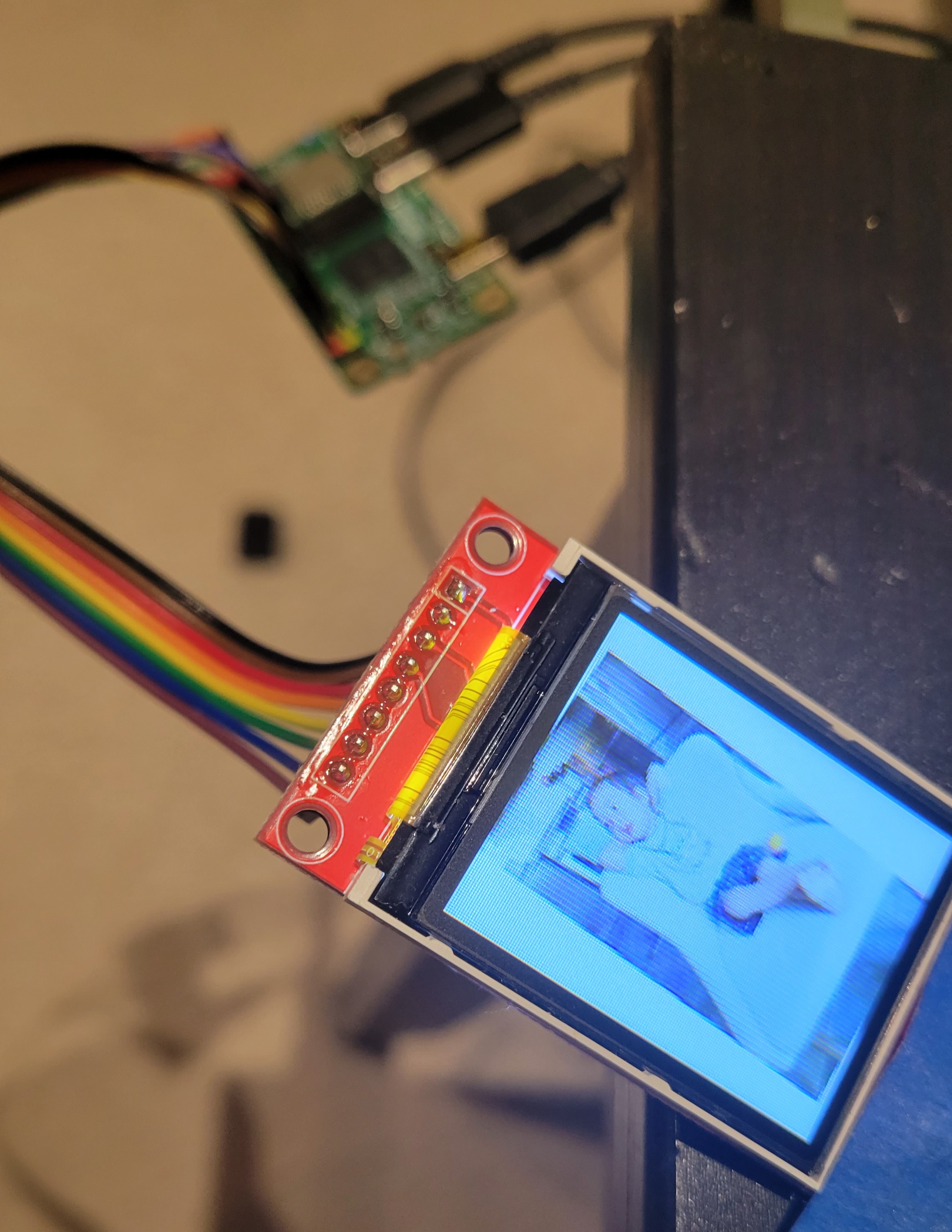
…I was able to get what looks like “snow crash” on my display after reading up and moving some pins around today. I am still not sure where DS, RST, and BL, should go though. It really sucks that no one reads this forum.
It’s really depending on your display. But generally power goes to power, ground goes to ground, SPI goes to SPI, and the rest are usually any free GPIO pins. I have no idea what DS or BL stands for, but using this Waveshare display as an example:
- SI/SO/CLK/CS are SPI pins
- 5V/3.3V/GND are power pins
- NC stands for not connected
- rest are control pins that can be connected to GPIO pin, but requires device tree overlay and driver to properly control them
I’m trying to get a Waveshare 2" SPI TFT display working, with screen dimensions of 240v, 320w.
I’m attempting to use the instructions presented in the repository here: https://github.com/mrkprdo/radxa-zero-spi-display
There are no instructions available from Radxa directly on how to do this.
Okay - a very careful reading on the instructions gives me what I think is a complete understanding of how it’s supposed to work.
-
Install the Radxa official Ubuntu bootable distro (“Buster”).
Open a terminal shell and access your root account. Everything else you do will be via this open shell.sudo bashshould do the trick. Change to your home directory withcd ~. -
Set up wifi via the main console (keyboard, mouse and screen). Access rootTo do this, open a shell and type:
nmcli dev wifi connect <yourWifiMountPointName> password <yourWifiPassword> -
You can update your repository, but DO NOT UPGRADE anything. If you do, you can end up with multiple kernel-specific directories for different kernels. Only the currently active kernel as described in the /boot/uEnv.txt file will matter, so there’s no point in upgrading the kernel before you get this working the first time. Change as few variables as possible while you fiddle with it, then migrate the changes to the new kernel if you want to update the kernel afterwards.
-
Install git, the device tree compiler, and the framebuffer command line tool:
sudo apt install git fbi device-tree-compiler -
Use
gitto get the repository from Github:
git clone https://github.com/mrkprdo/radxa-zero-spi-display -
Navigate to your device tree path:
cd /boot/dtbs/5.10.xx-x-amlogic-xxxxxxxxxxxxx/amlogic/overlay -
Copy the sample .dts file from the repository you cloned into the current directory:
cp /root/radxa-zero-spi-display/meson-g12a-spi-lcd.dts . -
Edit the file meson-g12a-spi-lcd.dts, and edit the screen dimensions to match your device. Mine has a width of 320 pixels and a height of 240 pixels.
Now this is where things get fuzzy.
- The instructions suggest changing pins for to something one looks up from a header file located at https://wiki.radxa.com/Zero/hardware/gpio, and they say that the value here should be GPIOH_8 for the Radxa Zero. Then we are told to check to see whether we should set it to initialize it as either HIGH or LOW, and that this second value should be 1 or 0 respectively.
Unfortunately exactly how we check this, or where to find this out, isn’t covered in the instructions.
Also unfortunately, nothing in the .dts file actually matches <pin>, and there is no inkling as to what this means. I am assuming they mean reset-gpios because it’s already set for <0x2b 8 1>, but it’s a leap of faith because I don’t know what <0x2b 8 1> actually means in context.
-
After that, we are told to save the file and compile it to a dtbo file (ignoring the warnings - it generates five of them).
dtc -@ -I dts -O dtb -o meson-g12a-spi-lcd.dtbo meson-g12a-spi-lcd.dts -
Then you update the file
/boot/uEnv.txtto tell it to load the new overlay meson-g12a-spi-lcd, adding the following contents if missing (do not create a second “overlays” parameter line, just appendmeson-g12a-spi-lcdif it’s not present. Separate overlay names with spaces, not commas.):
overlays=meson-g12a-spi-lcd
param_spidev_spi_bus=1
param_spidev_max_freq=10000000 -
Save the file, then go to the code repository you’ve downloaded from Github and run the “make” command:
cd /root/radxa-zero-spi-display/kernel-linux-5.10.y-radxa-zero/drivers/staging make
This will produce the two .ko files you need. -
Copy fbtft.ko and fb_st7789v.ko to the staging directory for your currently active kernel:
cp fbtft.ko /usr/lib/modules/5.10-xx-x-amlogic-xxxxxxxxxxxxx/kernel/drivers/staging -
Now all you have to do is reboot:
reboot now
If one does do an apt upgrade, one gets a second modules directory under /usr/lib/modules for a new version of the kernel, and a new subdirectly under /boot/dtbs into which one must copy the code for the device driver and compile it. The /boot/dtbs and /usr/lib/modules directory contents must be in sync or the magic trick does not work.
Anyway, when it comes back up, you should be able to see it via dmesg:
dmesg | grep fbtft
For me, so far so good.
However, then we test the newly created SPI framebuffer device with the fbi command line tool:
fbi -d /dev/fb1 -T 1 -noverbose -a <sample_image> and that’s where I break.
If one follows the above steps exactly, it compiles and the modules load. However, there should be an /dev/fb1 device, and there isn’t one.
Apparently it’s related to the GPIO pin setting somehow. A search through the dmesg output produces several error messages to this effect:
[ 0.069614] OF: /soc/bus@ffd00000/spi@15000/st7789v@0: could not get #gpio-cells for /soc/bus@ff600000/bus@34400/pinctrl@40/i2c3-sck-a1
Does this mean my Radxa is broken? Shouldn’t it be able to get GPIO cells from the pinctrl device manager?
… and one important one bug that looks serious:
[ 7.088944] fb_st7789v spi1.0: error -EINVAL: Failed to request reset GPIO [ 7.099764] fb_st7789v: probe of spi1.0 failed with error -22
This error is probably why my device driver isn’t coming up, and I believe the problem may be related to step #10 above. Apparently the pinctl kernel module isn’t finding necessary GPIO data for the new device descriptors, but I can’t tell why. This is especially frustrating since others have followed the instructions and have apparently not hit this issue.
Anybody got any ideas?
Update
Apparently that’s exactly what it means: my Radxa is broken.
I have a defective Radxa Zero, because when I tried the entire above process on a second unit I had on hand, I got no GPIO error messages. However, now I have a new error when I try to use the fbi command line tool to display a graphics file:
fe-dai-link-0: ASoC: no backend DAIs enabled for fe.dai-link-0
This appears to be a kernel bug, but the version of the kernel I’m using isn’t supposed to have it. I also don’t know if it’s related at all to the SPI display not displaying anything, but it’s now the only error message I have.
My SPI display backlight lights up when the Radxa powers up, but otherwise it does nothing.
I’m following the connection directions from Waveshare as described here.
BL stands for Backlight.
DC stands for Display Clock (I think you meant DC)
The reason there is no instruction is because when I tried to follow and reproduce those guide I couldn’t get SPI display to work myself. The best I got was a /dev/fb1 with backlight on. However, the image is corrupted in strips, so that feels like some kind of timing issue.
Here is the code that I created back then. This installs fbtft driver as dkms module, and compile the dtb overlays. My test was done with meson-g12a-spi-ili9486.dts since that’s the screen sample I had back then.
I notice that the ST7789v driver is there too. I’ll try it, it’s worth a shot.
I have not touched my zero for a long time. Let me get back to it and try this again. And hopefully, i can get some proper guide or perhaps provide the drivers to make this work.
That would be pretty amazing, Mark!
I hope you find my detailed technical description of what I did and how it went useful.
You’re a mensch.
I’m using a Waveshare 2" display, with a resolution of 240x320.
Update:
Retried compiling and installing the kernel/driver for my LCD, but couldn’t get it to work now. Tried using latest available kernel installed on top of the one that came with the os (Ubuntu focal). It shows error like this:
fbtft: version magic '5.10.69-12-amlogic-g98700611d064 SMP preempt mod_unload aarch64' should be '5.10.69-13-amlogic-g104342c59952 SMP preempt mod_unload aarch64'
But using 5.10.69-12 kernel version at least i can get it to load the lcd kernel and device tree overlays. I can see it writes to the framebuffer (created /dev/fb1) when i test it with fbi commands. However it is not showing anything on my lcd, i have two 128x160 st7735s both didn’t work.
I tried to use the same setup from when I got it to work and was able narrow it down to the only thing that’s left to test is to use the older kernel version (5.10.69.4 < kernel version < 5.10.69-12). Unfortunately it no longer exists in radxa’s apt repository and I have no idea where to get it.
One thing to note that I might have missed or vaguely explained in my steps is the part where you get the values for the pins, for example:
reset-gpios = <0x30 8 1>; for reset pin
To explain it further we need to grab it from the installed kernel’s dto and the pin assignment, focus on the value 0x30.
0x30 - this can be found here:
cd /boot/dtbs/5.10.69-xxxxxxx/amlogic
sudo dtc -I dtb -o dts -o meson-g12a-radxa-zero.dts meson-g12a-radxa-zero.dtb
open the file thats generated called meson-g12a-radxa-zero.dts, and do a text search for the word meson-g12a-periphs-pinctrl. Within the text under that, look for the keyword bank@40 and under that take the value from phandle = <0x30>;. That 0x30 is what you are looking for.
For values 8 and 1, I should have it explained in the original steps.
Again the result of my attempt to run this again is not successful in the sense that I can load the driver and see that it starts in dmesg, loads /dev/fb1, and tries to write values to my LCD but is not showing anything on my screen.
If someone can point out to me where / how to get those older kernels just to see if my theory on newer kernels can’t load LCD driver, that would be great.
Ok after few times going back and forth. I found the problem and got it to work again.
Edit.
Will try to update the guide later.
This is exciting news! Especially since your previous two posts imply that you didn’t actually need to revert to a previous kernel to make it work.
I was a professional technical writer for a motion picture studio for ten years, and I’d be happy to help you revise the instructions to make them accessible to the less experienced experimenter should you wish it. No judgment.
I’ll tell you though, if the outcome of this is a well presented, foolproof instruction guide you can boost the entire Radxa community. In particular, the lack of formal SPI support for displays is a showstopper for a lot of experimenters who might otherwise want to use the Radxa in special projects.
Radxa themselves might want to adopt the results as official documentation if this all works out. That’ll take the Radxa community as a whole to the next level.
1 Like
I have to start from a clean slate, and created a simple script that will atleast automate the setup.
Refer to this new repo:
This is not perfect build simplifies the process. This worked on kernel version: 5.10.69-13-amlogic-g104342c59952
I got it to work with ST7789 lcd, my ST7735 seems broken since i could not run it again after I was able to rebuild the driver for it which is weird.
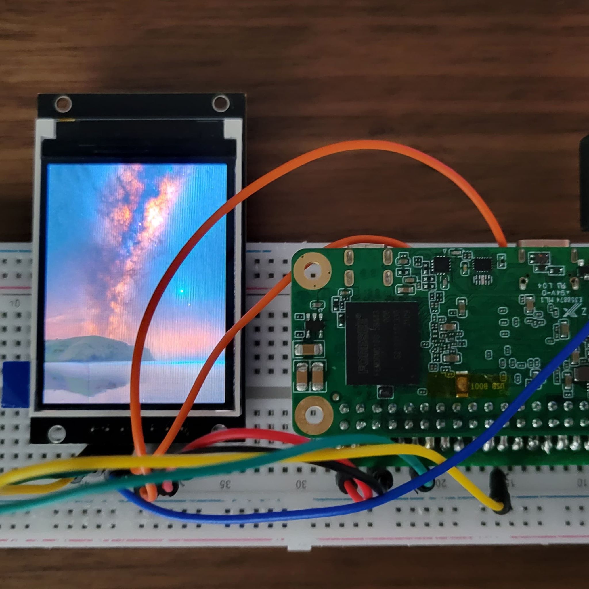
The new script runs on my Radxa, and everything appears to work - except there’s no display.
This leads me to believe that I have the wiring wrong. Is there a diagram someplace that shows how you hooked yours up? I’ve checked mine a bunch of times and can’t find the issue.
Ahh forgot to mention pin config, here is the setup:
VCC - PIN 4 5v or PIN 1 3.3v
GND - PIN 6
DC/AO - PIN 12
MOSI/SDA - PIN 19
SCLK - PIN 23
SS0/CS - PIN 24
RESET - PIN 35
LED - PIN 17
Hmm - my Waveshare is labeled
VCC
GND
DIN, or “data in”, translates to Master In / Slave Out (MOSI), or Pin 19 on the Radxa
CLK
CS
RST
BL
I had to look up what the translations on these are supposed to be. The only one I couldn’t figure out was DIN, which turns out to have been the MISO/SDA pin.
And yeah, I had mine connected wildly wrong.
–
UPDATE: I apparently STILL have it wrong, because everything works but there’s no display. This time dmesg contains no errors and it looks like the st7789v device is properly registered and functioning, and the drivers and descriptors installed without a hitch and produce no runtime errors.
At this point I’m off the highway and I’ve run out of dirt road. There are no trails left to follow as far as I can see from here. Anybody got an idea where I should be looking for my next clue?
I get the sense that I’m still missing a step here.
Is your backlight on?
Can you share your lcd screen make/model?