Retried compiling and installing the kernel/driver for my LCD, but couldn’t get it to work now. Tried using latest available kernel installed on top of the one that came with the os (Ubuntu focal). It shows error like this:
fbtft: version magic '5.10.69-12-amlogic-g98700611d064 SMP preempt mod_unload aarch64' should be '5.10.69-13-amlogic-g104342c59952 SMP preempt mod_unload aarch64'
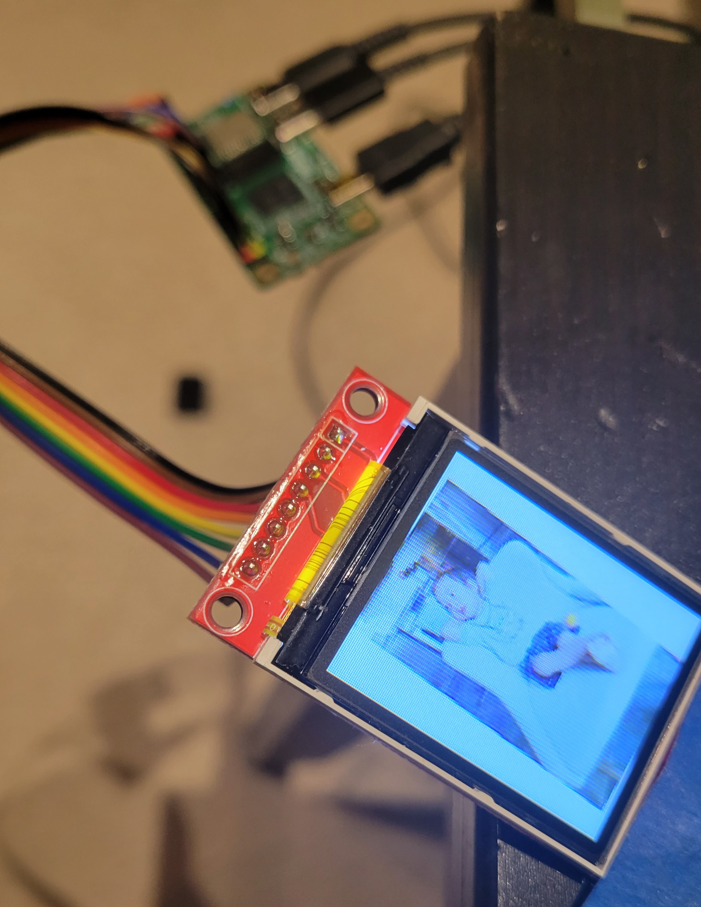
But using 5.10.69-12 kernel version at least i can get it to load the lcd kernel and device tree overlays. I can see it writes to the framebuffer (created /dev/fb1) when i test it with fbi commands. However it is not showing anything on my lcd, i have two 128x160 st7735s both didn’t work.
I tried to use the same setup from when I got it to work and was able narrow it down to the only thing that’s left to test is to use the older kernel version (5.10.69.4 < kernel version < 5.10.69-12). Unfortunately it no longer exists in radxa’s apt repository and I have no idea where to get it.
One thing to note that I might have missed or vaguely explained in my steps is the part where you get the values for the pins, for example: reset-gpios = <0x30 8 1>; for reset pin
To explain it further we need to grab it from the installed kernel’s dto and the pin assignment, focus on the value 0x30.
0x30 - this can be found here: cd /boot/dtbs/5.10.69-xxxxxxx/amlogic sudo dtc -I dtb -o dts -o meson-g12a-radxa-zero.dts meson-g12a-radxa-zero.dtb
open the file thats generated called meson-g12a-radxa-zero.dts, and do a text search for the word meson-g12a-periphs-pinctrl. Within the text under that, look for the keyword bank@40 and under that take the value from phandle = <0x30>;. That 0x30 is what you are looking for.
For values 8 and 1, I should have it explained in the original steps.
Again the result of my attempt to run this again is not successful in the sense that I can load the driver and see that it starts in dmesg, loads /dev/fb1, and tries to write values to my LCD but is not showing anything on my screen.
If someone can point out to me where / how to get those older kernels just to see if my theory on newer kernels can’t load LCD driver, that would be great.
This is exciting news! Especially since your previous two posts imply that you didn’t actually need to revert to a previous kernel to make it work.
I was a professional technical writer for a motion picture studio for ten years, and I’d be happy to help you revise the instructions to make them accessible to the less experienced experimenter should you wish it. No judgment.
I’ll tell you though, if the outcome of this is a well presented, foolproof instruction guide you can boost the entire Radxa community. In particular, the lack of formal SPI support for displays is a showstopper for a lot of experimenters who might otherwise want to use the Radxa in special projects.
Radxa themselves might want to adopt the results as official documentation if this all works out. That’ll take the Radxa community as a whole to the next level.
The new script runs on my Radxa, and everything appears to work - except there’s no display.
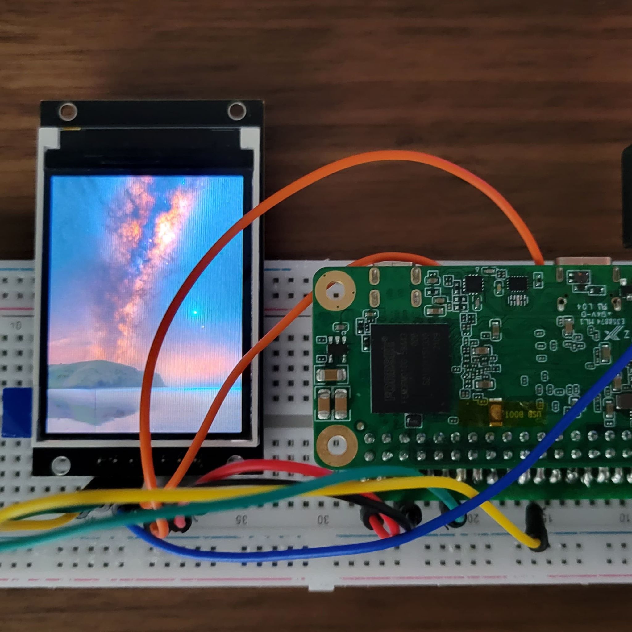
This leads me to believe that I have the wiring wrong. Is there a diagram someplace that shows how you hooked yours up? I’ve checked mine a bunch of times and can’t find the issue.
Hmm - my Waveshare is labeled
VCC
GND
DIN, or “data in”, translates to Master In / Slave Out (MOSI), or Pin 19 on the Radxa
CLK
CS
RST
BL
I had to look up what the translations on these are supposed to be. The only one I couldn’t figure out was DIN, which turns out to have been the MISO/SDA pin.
And yeah, I had mine connected wildly wrong.
–
UPDATE: I apparently STILL have it wrong, because everything works but there’s no display. This time dmesg contains no errors and it looks like the st7789v device is properly registered and functioning, and the drivers and descriptors installed without a hitch and produce no runtime errors.
At this point I’m off the highway and I’ve run out of dirt road. There are no trails left to follow as far as I can see from here. Anybody got an idea where I should be looking for my next clue?
I get the sense that I’m still missing a step here.
I’ve gone over the wiring and conformed it to what you specified. The backlight works, so it’s certainly getting power, and dmesg isn’t reporting any issues like it did last time (with what was apparently a defective Radxa Zero), so I’m stumped.
In waveshare’s documentation page, it says:
RESX: the reset pin, it should be low when powering the module and be higher at other times;
D/CX: data/command control pin, when DC = 0, write command, when DC = 1, write data
Can you play around with the values setting them 1 or 0 in the dts file,
reset-gpios = <0x30 8 1>;
dc-gpios = <0x30 74 0>;
Also make sure you have the correct phandle values of the kernel you are running it from.
Edit:
I can’t really troubleshoot you situation as I dont have exact same lcd screen. (also cost 20$CAD so wont be getting that one). Another way to troubleshoot is really tap on the SPI connection and see if you have some signals coming out, not trying to go deeper and parse out the signal, but may trying to inspect if you have indeed a working framebuffer not a broken display. Otherwise it can be that the display is broken. I used this Signal Analyzer, works great for debugging signals.
I’m also strugging to get an LCD display to work. I did a previous topic on loading DT overlays. Now the device-tree processing part is clear, but I still don’t get a /dev/spidev0,0 device file on the system - a plain ArchlinuxArm with a vanilla linux-aarch64 kernel.
I will follow your advice to try and talk to it on the lines.
Other thing I tried recently : boot latest Ubuntu server edition. There I get the spidev1,0 device, but when using it with gpiod as root it fails (see log below). I specially ported a script to gpiod to make sure it works on a Raspberry Pi 4B. I’m using it with a Waveshare 1in44 LCD pHat, so the pins are static.
Traceback (most recent call last):
  File "qr.py", line 10, in <module>
    from gpiod_lcd import LCD_1in44
  File "/home/lafleur/source/radioboite/gpiod_lcd/__init__.py", line 3, in <module>
    from gpiod_lcd.LCD import LCD, LCD_1in44, LCD_1in8
  File "/home/lafleur/source/radioboite/gpiod_lcd/LCD.py", line 36, in <module>
    _raw_screen = LCD_GPIO()
  File "/home/lafleur/source/radioboite/gpiod_lcd/LCD_GPIO.py", line 52, in __init__
    self.bl_pin = LCD_GPIO._request_pin_out(LCD_BL_PIN, "BL")
  File "/home/lafleur/source/radioboite/gpiod_lcd/LCD_GPIO.py", line 75, in _request_pin_out
    line.request(config)
  File "/usr/local/lib/python3.8/dist-packages/gpiod/libgpiodcxx/__init__.py", line 572, in request
    rv = libgpiod.gpiod_line_request(_m_line, conf, default_val)
  File "/usr/local/lib/python3.8/dist-packages/gpiod/libgpiod/__init__.py", line 499, in gpiod_line_request
    return gpiod_line_request_bulk(bulk, config, [default_val])
  File "/usr/local/lib/python3.8/dist-packages/gpiod/libgpiod/__init__.py", line 542, in gpiod_line_request_bulk
    return _line_request_values(bulk, config, default_vals)
  File "/usr/local/lib/python3.8/dist-packages/gpiod/libgpiod/__init__.py", line 403, in _line_request_values
    status = ioctl(fd, GPIO_GET_LINEHANDLE_IOCTL, req)
OSError: [Errno 16] Device or resource busy
I think if you have to work on SPI natively without needing to compile your own device tree overlays or kernel driver, you might need to look at libmraa to interface with spidev. With that you can probably define pin assignments and be able to use python wrappers and use it for your stuff.
I have strong reserves against libmraa because I had erroneous display with the same Waveshare LCD on a RPi4, whereas both RPi.GPIO and libgpiod succeeded (same hardware, same pin assignment). Would you say libmraa has capabilities the two others don’t ?
@mrkprdo In the end I followed your advice and succeeded in piloting my display using libmraa. I’m running Arch Linux and found a working mraa PKGBUILD for Radxa boards on the AUR. I’ll still try to port my script to libgpiod because it feels better integrated in Arch systems ; that will be another story.
As you mentioned, there is no need to compile a specific DT overlay to get SPI display support. I can witness SPI_A works fine using the default overlay. It’s just that the display’s connection instructions I had (written for a RaspberryPi) need to be adapted - specifically, the instructions I had said to use physical pin 22, but this pin is an open drain on the Radxa Zero, which makes it unsuited for input/output as is (followers, see Radxa Zero GPIO specifics).
In the end, what’s unclear to me is when are your LCD driver or SPI display instructions needed - or what benefit they would bring over using the default overlay together with hardware-specific libraries. As @SCIFI.radio mentioned, there would be a need for newcomers’ documentation on this subject. I hope that my questions will help us understanding what happens in a newcomer’s head
Anyway thank you very much for pointing me in the right direction !
That’s good to hear you have made it to work.
The SPI display instructions i made is to compile dto with fbtft kernel driver and use the display as framebuffer. End goal is to make these displays as monitor like this.. But unfortunately radxa zero spi is quite slow.
I just debug the st7789vw lcd on my radxa zero,It’s running ok,but there is some issues should be avoided:
the reset pin on ZERO should be careful of these open drain pins
It seems difficult to compute or look for the phandler value of the first gpio group,if
U want use these pins as dc or res pins for tft lcds.
3.the ko file should be compiled on you host machine,or the magic problem of linux driver would bother you all times