Without any MMC/SD/SSD connected and no USB peripherals plugged in, and without pressing any button when booting, it should make serial port (TTY) output on boot shouldn’t it - do you have any thoughts what to debug? Eg @jack
Per the suggestion at https://wiki.radxa.com/Rock5/FAQs#Boot , I tried to connect the USBC power connector to a computer and see if any device shows up, outside and in MASKROM mode, and indeed a PCI device shows up - based on this test, this Rock5B does work, it’s not defective.
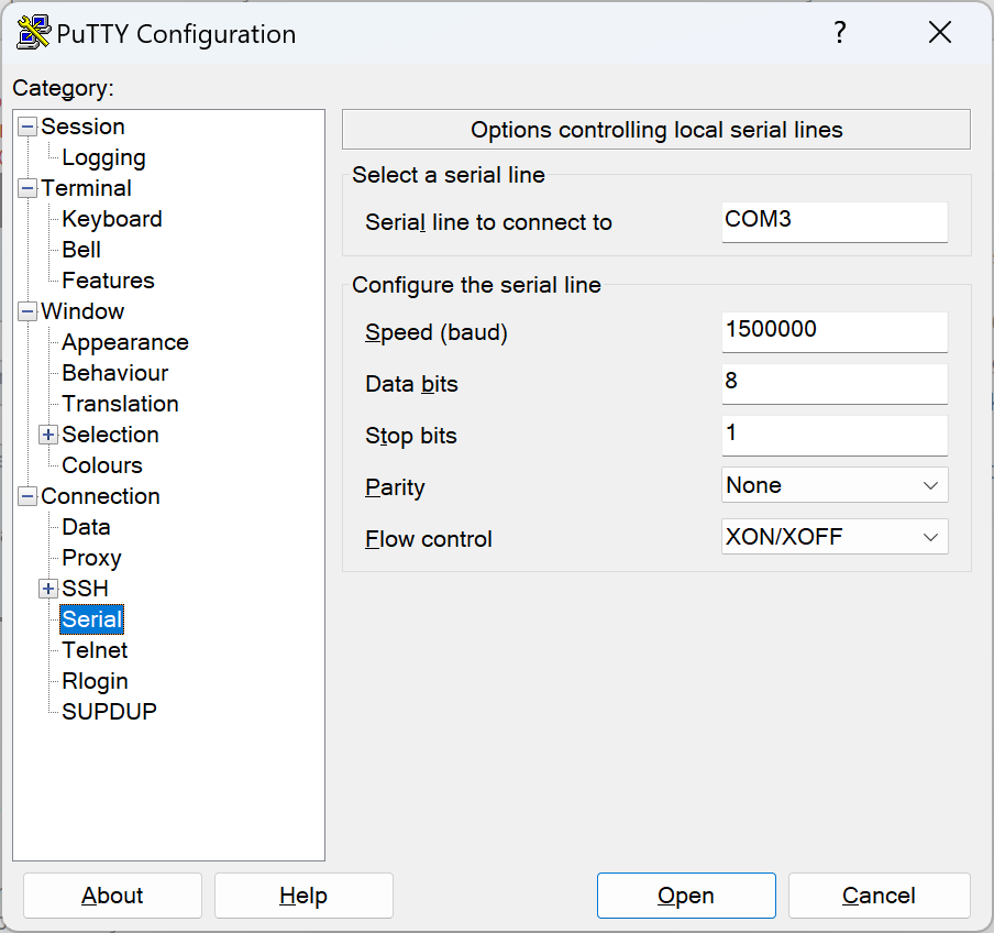
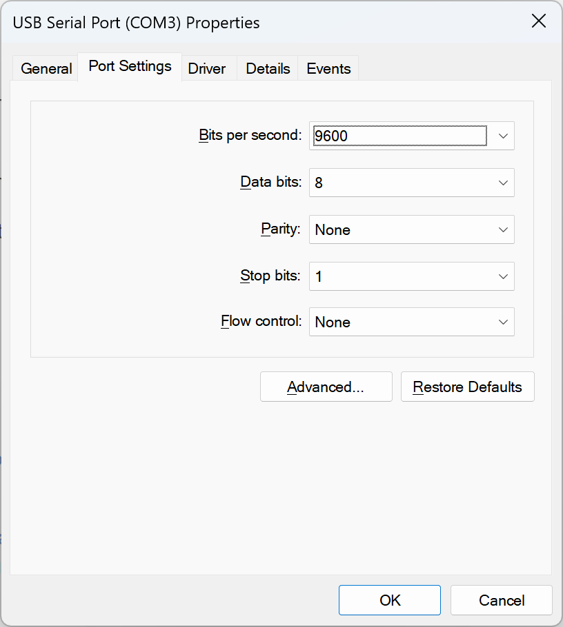
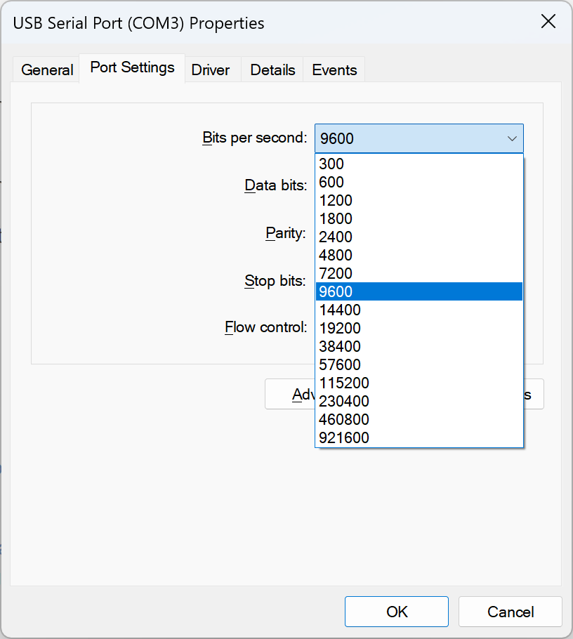
Putty will override the baud rate when you set the baud rate inside the Putty connection options before you connect.
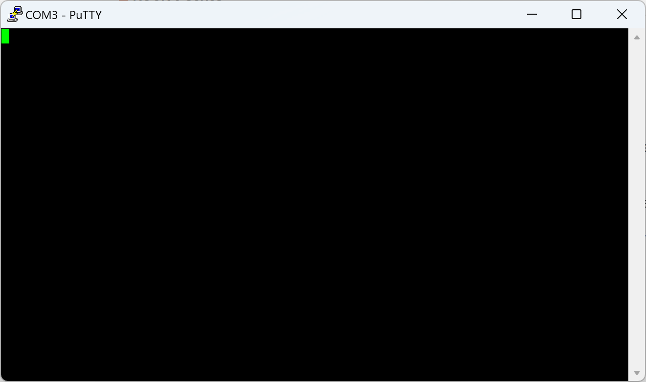
It is normal not to see any TTL output if you haven’t flashed the SPI NOR or connected a pre-flashed SD card or EMMC flash ram to the machine. If you haven’t flashed the SPI NOR and you didn’t provide a flashed SD card or EMMC flash ram then the board will boot up in Maskrom mode. When the board is in Maskrom mode, you won’t see any serial output and the blue LED will not come on at all. You will see a solid green LED only.
You can find instructions on the wiki to program the SPI NOR in Maskrom mode.
You can test the basic functioning of your TTL cable by disconnecting the TTL cable from the rock5b and connecting the TX of your debug cable to its RX to verify normal operation. Putty should then echo whatever you type on its terminal back to you if the device works properly.
To get any TTL debug output out of the Rock5b you will have to flash the SPI NOR that is built-in with the u-boot firmware or you will have to connect a flashed SD card or EMMC card that will have the u-boot bootloader as well as a Linux image to boot off of. When u-boot boots on the machine the LED should turn blue and you should start seeing TTL debug output if your serial cable is connected properly. If you also have a radxa OS image on some device (SD, EMMC, USB, NVMe, PXE etc) and it is able to boot into an OS then the light will turn green and flash blue twice each second or so.
@matt911 Many thanks for your pointers. I got it to work now, via the route of flashing the eMMC to an image and then booting. This worked at first on the second boot, as there was a glap in the eMMC socket on the first try. Thanks especially for reminding that the LED will blink when Linux booted, indeed it does.