Test of the AI PC kit

Hi!

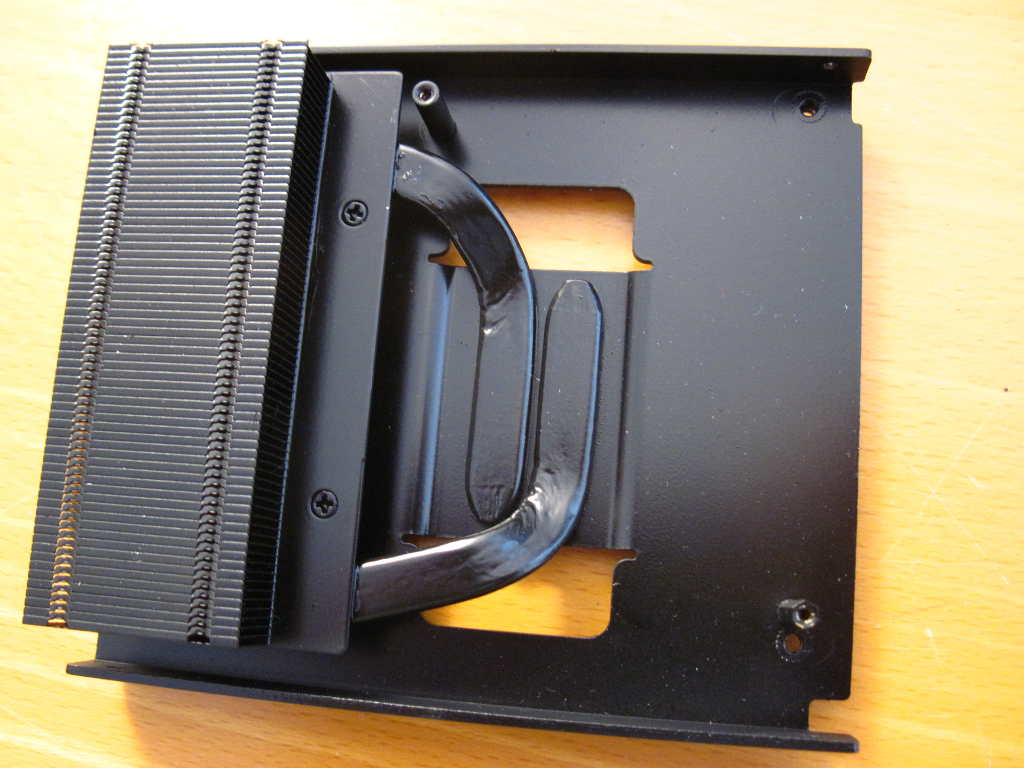
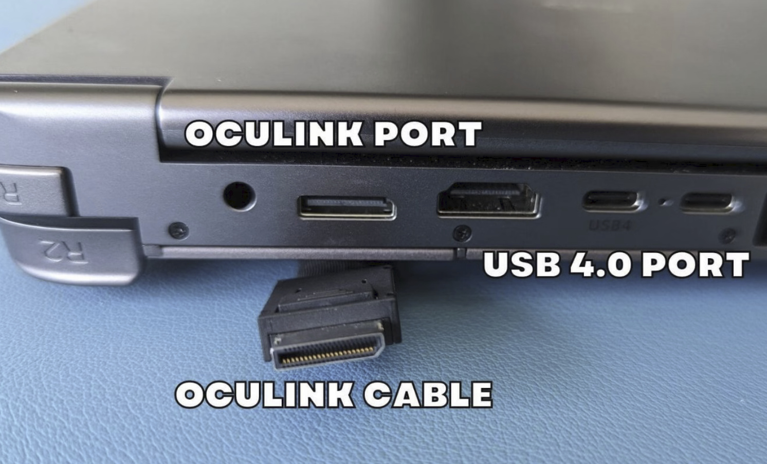
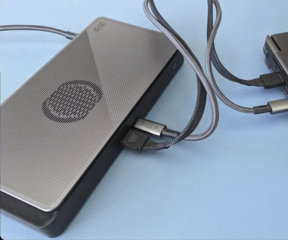
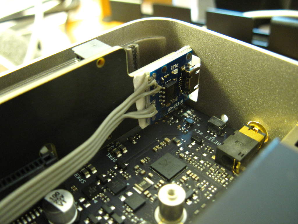
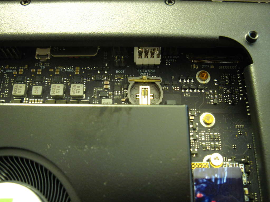
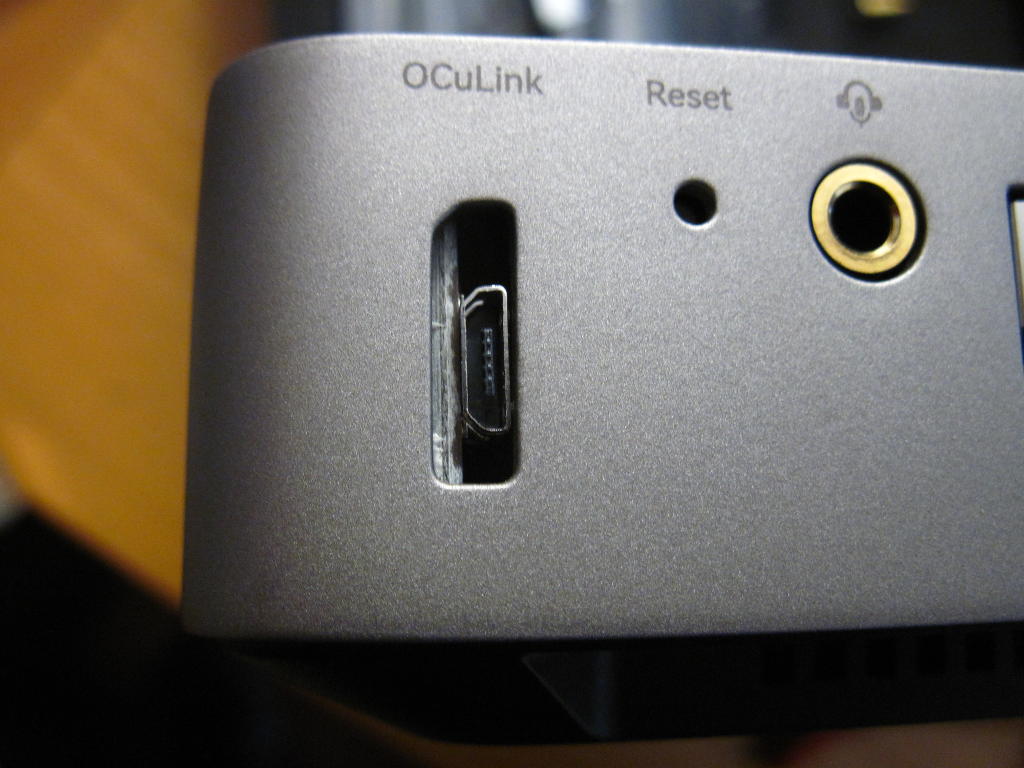
I received an AI PC kit (the metal enclosure for O6). Thanks for this! I mounted my board in it. It’s really well designed and perfectly matches the board’s ports. I could use the oculink hole at the rear to install a USB-UART adapter connected to UART2 for the console that I stuck to the M.2 adapter. Both USB-C and micro-USB fit fine through that hole. Also the internal metal armature arrives just on top of the UART2 connector but there’s enough room even for a moderately large connector, as seen below:

One thing I noticed is that the included fan is more silent than the original one when idle, which is appreciable, however it significantly noisier when it’s hot. The sound is higher-pitched probably from the finer fins and the plastic grid on the output, but stops when the temperature falls again. I’ll have to see with time if I find it annoying or not. I don’t remember being disturbed as soon by the original one when compiling.

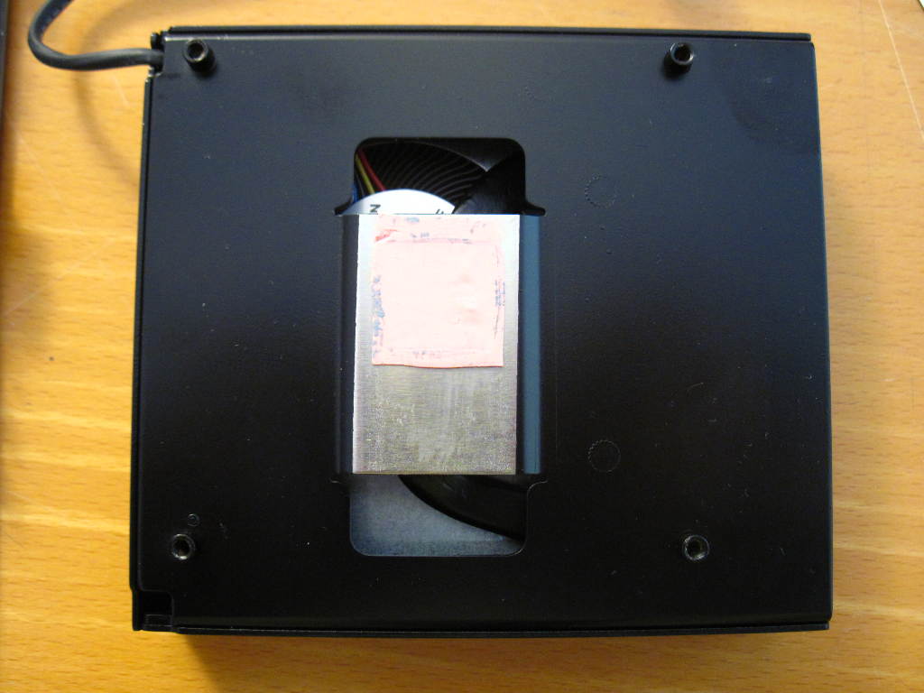
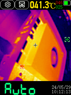
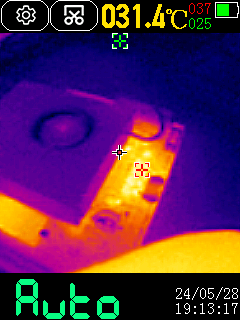
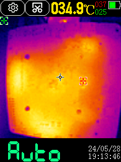
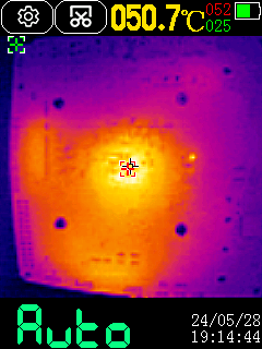
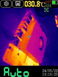
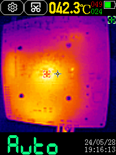
However I noticed a more annoying problem. Building haproxy caused the fan to immediately speed up and the machine to hang in 5 seconds. I tried again, while monitoring temperatures, and it one of the clusters reached 97°C just before hanging, with 92 and 90 for two others. I took an IR capture of the board at the top, then at the bottom, first in idle, showing 34°C, then during builds where it was already at 50°C 5 seconds later when hanging:
IR_0039 IR_0040 IR_0042

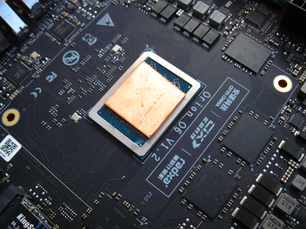
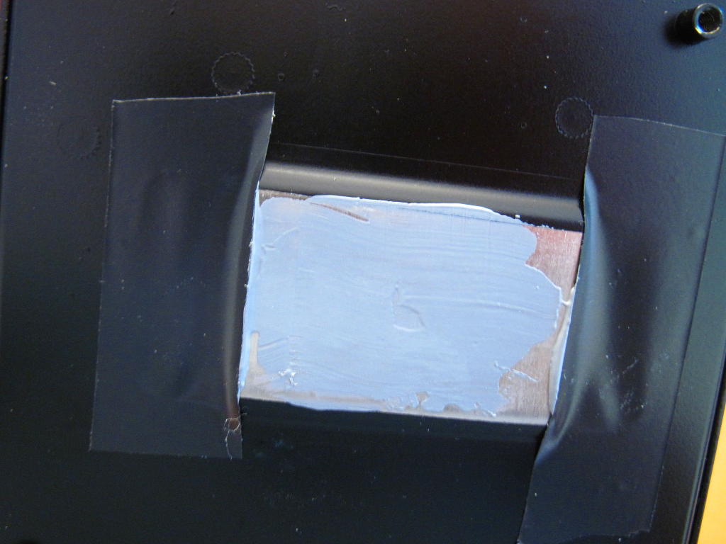
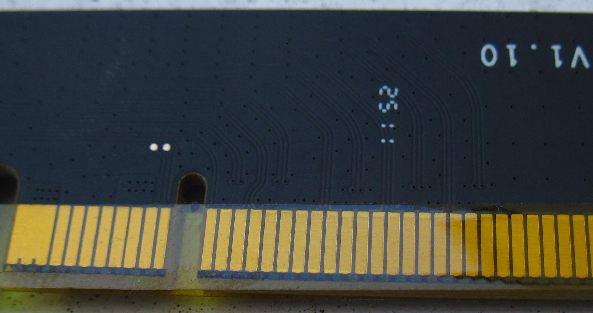
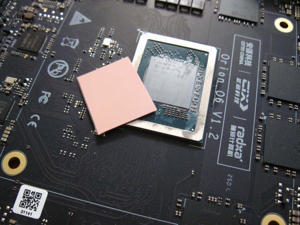
I had noticed already while positioning the heat sink on top of the SoC that it didn’t seem to press much against it, because the 4 screwing feet already touched the board before inserting the screws. So I disassembled it, removed the thermal grease and added a thin thermal pad on top of the silicon die:

I reinstalled everything and ran the same test several times. This time the temperature didn’t go beyond 85/83/82, i.e. roughly 12 degrees less than with the grease only. (don’t be worried about these numbers by the way, it is expected as my board is a bit overclocked (3.1+3*2.6) and is 100% reliable with the original heat sink). Now there was no heat problem anymore, and the IR cam showed a difference, the fan is hotter and the bottom is colder:

IR_0044 IR_0043

I don’t really know if it’s only the heatsink’s feet that are too long (at least I think it does count since there’s no margin to pressure it against the board). I’m also wondering if the die is at the same level as the surrounding metal around the SoC or not. With that said, the original heat sink was not facing any problem and was completely flat, so maybe it’s just a matter of removing 0.25mm of height to the feet to secure the new heatsink correctly.

Last point, I know that there exists thick thermal pads. I know I have one somewhere but I couldn’t find it. They’re suited for use directly underneath PCBs, regardless of the presence of small caps. Here given the layout of the enclosure, it would be really nice to place one below the SoC (1.5-2mm high I guess, for 1 sq inch), in order to transfer some of the bottom heat directly to the top of the enclosure. Usually it’s possible to transfer a few watts using such solutions, I’ve used that to cool some SBCs already. It might even help the fan start later.

Hoping this helps!

3 Likes

Thanks! Been waiting for someone to receive their AI Kit to see how it is.

Didn’t realize it came with a different fan - appreciate your notes on that.

1 Like

Yes, the kit is detailed here (I should have pointed that), which is why I didn’t take photos of the parts:

https://docs.radxa.com/en/orion/o6/getting-started/ai-pc-kit-usage

Honestly it’s well designed.

The fan is much more sensitive than the original one. My original one starts at pwm=17, this one starts at pwm=10. Till 16 you simply can’t hear it at all an only see it rotate. At 17 you start to hear it very faintly.

Why there are so many issues with thermal design and space between SoC and heatsink? :frowning:
Radxa X4 also needs small copper plate to improve heat dissipation, helps a lot!

You would like to transfer some heat to enclosure?
This is not always possible due to regulations in some countries, would be little odd to burn a bit hands if everything heats up too much and fan fails. Of course it’s great lifehack, especially for metal enclosures in rack switches :wink:

1 Like

I wasn’t aware. I’m seeing short peaks at 88, and I suspect that the thermal pad is not that good, because the fan at full speed blows cold air. I should have some copper plates somewhere in a box, I’d like to try with these and see if it changes anything. I have not found how to set the max fan speed to reduce it and keep the box quieter (especially if it doesn’t change the resulting temperature that much).

yes.

I didn’t know. I can understand but at some points there are limits though. When the surface is wide enough, it becomes a heat spreader and the temperature will not burn a hand. And there are many fanless enclosures for atoms and mid-power x86 which are designed like this with fins etc. Just look for “fanless” on aliexpress to see hundreds of them. Even the mcbin from Solidrun was like that (with no fins, just straight lines). An option could be to distribute the pad and say “if you’re not in these countries you can install it” :slight_smile:

I also noticed that the temperature is not much different with fan at low speed and full speed, because it takes about 5s to start when I run stress-ng, and the temperature had already stabilized to approx 85 and doesn’t go down. I’m still suspecting that the air flow through the whole device might be a little bit limited for cooling, as the air input is quite close to the table, so is the exhaust.

Copper is great for such use case, not that easy to use as soft thermal pads, but as always can be mixed with those if too thick thermal pad is needed.

As always You can do many things on Your own risk :slight_smile: Probably mostly this will not be a problem here, but it’s just general rule that You don’t expect 80deg on case, especially when it’s not in rack and kids are around.
Personally I think it’s worth to spread as much heat as possible with case, gaining some silence :slight_smile:

I was not expecting that high of course, at most 50. At 30W and for 30°C ambient, it would require a 0.66K/W heat sink to stay below 50, and I think that the current enclosure might not be very far from this.

1 Like

In fact I’m wondering if I couldn’t reinstall the original fan with a paper foil on top of it with a round opening only in front of the fan’s blades. This could suck the air from the bottom holes and blow them away on the back.

Sure thing,
probably not a problem here anyhow, unless You need any safety certification :slight_smile:
I would do that on my own (probably small) risk :slight_smile:

OK I disassembled the whole thing and installed a copper plate. There’s no comparison! Instead of reaching 85°C in 5s, it reaches 48°C. It’s now been running stress-ng on the 12 cores for one minute, and one cluster occasionally reaches 60°C. And this with the fan still spinning at a very low speed that nobody would complain about, even in a living room.

I must confess I had some doubts about the heat spreader. It’s made of two flat copper pipes between the pad that touches the CPU and the fins:

But as we’ll see, I was wrong, this part seems to be working pretty well in the end.

The real issue really is the pad itself which doesn’t touch the CPU well, and which is designed for larger CPUs:

As you can see on the photo above, the silicon die is only in contact with approx 1/3 of the flat pad surface, and it’s likely that its thermal resistance is not that good since it’s a thin aluminum plate (1-2mm thick at best). Also, there are holes which allow the fan to pick hot air from the SoC and board and recirculate it into the fins to try to cool them…

Thus I installed a 1mm thick copper plate on top of the die (with a thin layer of thermal grease of course). It’s larger than the die so that it will help make a larger contact with the heat sink:

I spread paste all over the heatsink’s pad, and using electrical tape I plugged the holes that allowed it to pick hot air from the bottom:

And now, after 25mn of running stress-ng on all cores (clusters at 3.1, 2.7, 2.6, 2.6, 1.8, 1.8 GHz), the hottest core oscillates between 63 and 64°C, and hot air goes out of the box, which is now cooler to the touch than before by the way (31.5°C). And the fan is still not at full speed, which is quite a relief for my ears. I stopped stress-ng at 25mn and the fan stopped almost immediately.

My guess is that the thickness of the copper plate is the most important factor here, to make a much better contact between the heat sink and the die.

I strongly suspect that this heatsink was designed for thicker x86 SoCs. I don’t know the level of customization that can be done on it (I’d assume that it will be difficult to file the screw legs). But
finding 0.5-1mm thick copper shims the size of the SoC to distribute with the kit would really do wonders IMHO. Here’s the thermal image after removing the bottom cover with stress-ng running. It blows air at 41.5°C while the SoC was running around 62, that sounds good.

IR_0045

At least now the AI kit enclosure is always better than the default one from a noise perspective :slight_smile:

3 Likes

Yet again small mod improves thermal a lot :slight_smile:
Thanks for tests and detailed report! :slight_smile:

Really appreciate the thorough write-up.

I plan on ordering the AI Kit and will probably try to do the same as you’ve done here.

I forgot to measure the area under the heat sink, I think it’s roughly 2x4cm. My recommendation for best efficiency would be to get copper plate of the whole surface, and stick it to the heat sink, so that the heat from the die spreads as widely as possible. 1mm thick is sufficient, and I think that 0.5mm would work as well (but copper might bend under pressure if too narrow). It could also be glued with some silicone-based thermal glue. There are also ceramic plates, but even the best ones are not as effective as copper (~230W/mK for AlN vs ~400W/mK for Cu).

I’ve got approximately the same temperatures by using a thermal pad. 1mm thick.

1 Like