I want to replace the motherboard of my Synology Nas (DS411j+) with a Rock Pi 4 A.
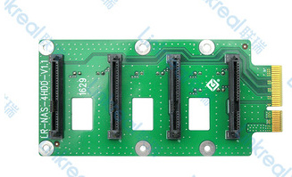
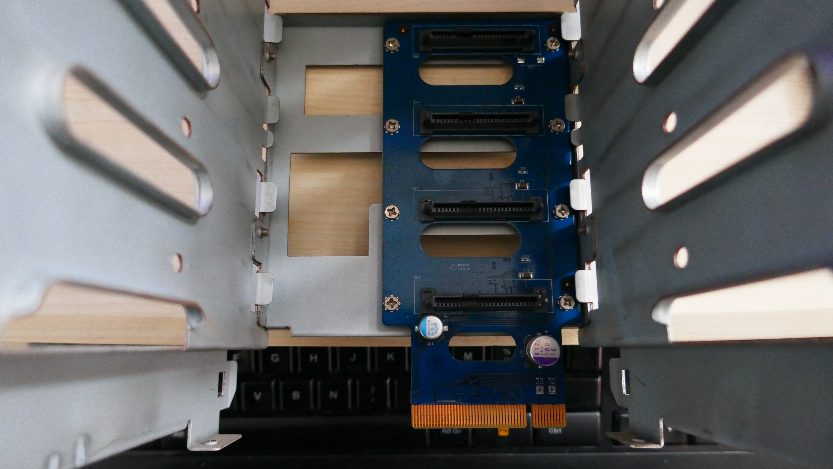
Due to the size of the Nas case, and the existing 4-disk rack, and since I would like to keep the Pcie -> 4 sata backplane card, as well as its power supply, I want to try a custom solution.
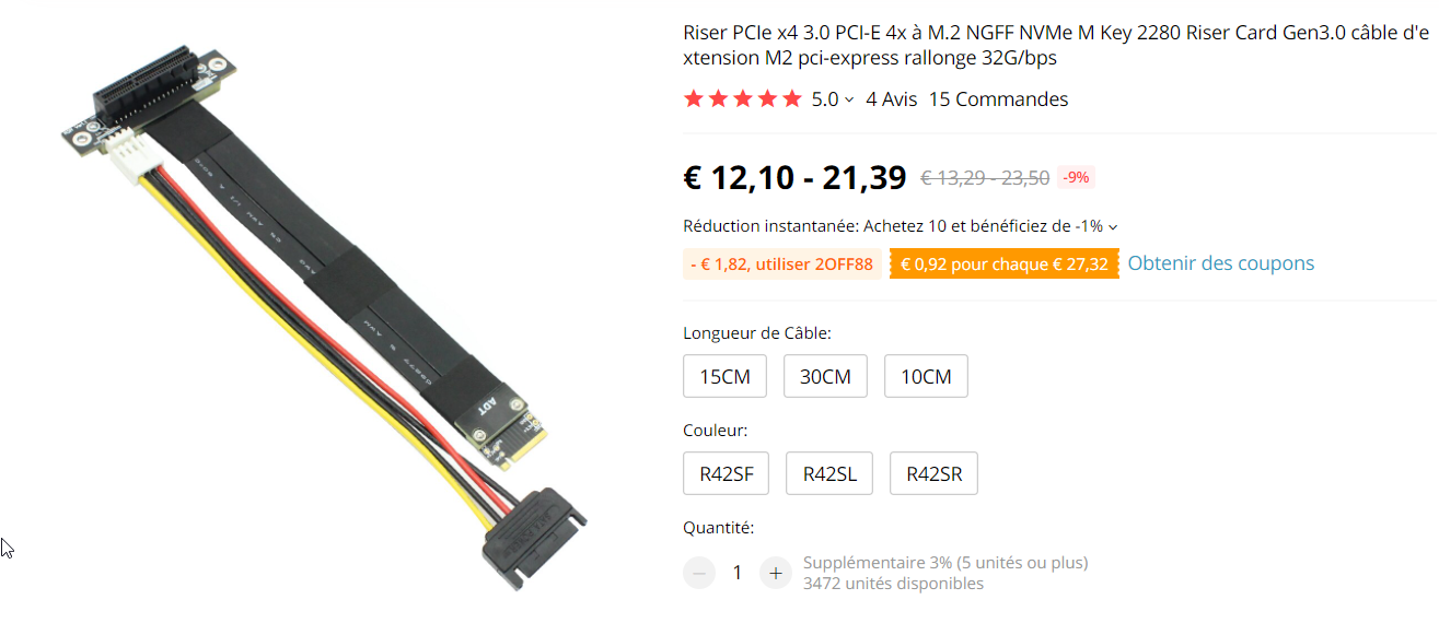
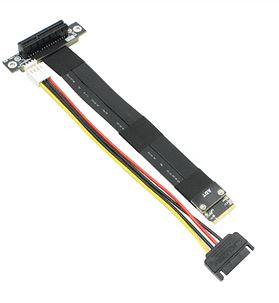
I’m trying to connect the m2 rock pi port to the PCIe/sata backplane card with a m2 to PCIe riser, and I want to use the original power supply of the syno (12V 8.3A).
My question is: is it possible to bypass the USB-C connector of the Rock Pi to supply it with 12V? It doesn’t seem possible with the GPIO port, so I would like to know if I can connect a 12V power supply behind the USB-C circuits.
Hi, thanks for suggestion
.
But my project are re-use maximum part of my Synology nas, if some part not working, I replace it by
SATA HAT and so.
But in first I want use the Synology back plate SSD, Synology case and rack and Synology power.
Hi, i’m waiting for parts delivery (1 Rock Pi4, 1 x SSD NVME expension card, 1 x Riser NVME to PCIe prolongator/adaptator.
During this time i’m thinking about re-use front leds and on/off switch on the Synology case.
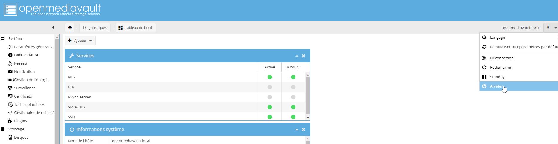
So im’ think modify 12v => to 5 V Buck converter used in Rock pi for be able to enable the Buck converter with the syno switch, and stop it with a service killed by OS (Open Media Vault) when it stop, the service set a GPIO output to 1 for stop the buck converter before exit.
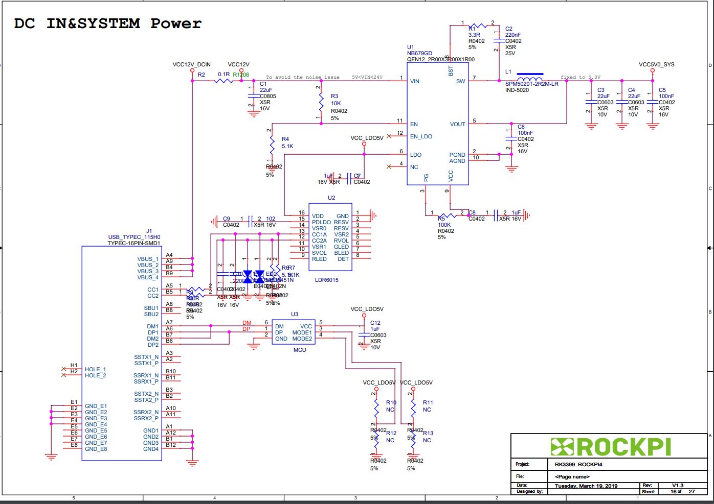
Schematique modification of power source of rock pi (buck converter used for 12v => 5v NB6790) for EN in and PG out, all parts not in this schema remain unchanged.
Explanations: when switch is pushed, EN of Buck is set to 1, the buck start, fews ms afer PG out is to 1 (+5v).that maintains EN to 1 (buck in function). When the OS is shutted down, it kill the service, the power service (need to be writed) set one GPIO output to 1 before exit, to have the NPN 2222 transistor set EN to 0 and stop the buck (10 microF capacitor is here for have a temporisation before shutdown the buck for leave time to the OS to finish it stop.
I’m found the 2222 transistor have to higher VCESat voltage for stop the buck, need to replace it with a another with VCESat < 0.4v (like A1015).
Im still wait for received mi rock pi and other eletronics parts, so i’m just do some tests for control all front leds panel of the syno (12 leds total) with the rock pi, and finaly choose to use only 3 GPIO out for control 16 leds with 2 x 74HC595 chained (2 x 8 bits deserializer with latch and carry report).
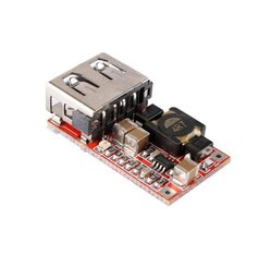
In the meantime i’m think about power supply all of that: the rock pi buck can deliver 5V - 8A, that’s huge, but i’m not want to charge it a lot and keep it safe if somethink bad arrived on the added electronics. So i’m think add a separated buck converter for power leds and hard disks (12 V=> 5V 6A).
The Syno power deliver 12V 8A, so it’s more than sufficient for all of that (15w max for rock pi, 60W for all drives…).
Connect the output to the RockPi4. For the LEDs, you can directly use the GPIO pins with current limiting resistors, 200Ohm should do fine.
If your synology SATA plate has a Molex connector, it would have been great, else, you will need a PCIe raiser with Molex connector.
EDIT: the PCIe raiser from aliexpress you posted seems to have external power input, in that case, you need to supply 12V in the yellow wire, 5V in the red wire, and connect GND to both the black wires.
Well, you are wirte for complicate think, i’m now think make an adapator cable for connect +12 from >Syno power block to USB-C.
first thanks for reply and made sugestion jayanta525.
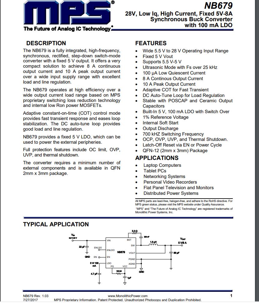
I’m think Rock Pi can handle 12v input, because the shematic diagram for Rock pi
clearly indicate it can, the NB679 Buck used in rockpi for produce the 5v can handle 28v input max, and the main limitating stuff is the 16v condensator used in rockpi for filter the 12v input.
5V for power the Rockpi is very few, the NB679 is rated for 5.5v to 28v.
The HDD are 3.5 " magnetic drives, so each consume arround 15w (mainly in 12v).
But i’m not want risk overload the 5v buck converter of the rock pi.
Anyway i’m need to plug 12v on the riser for power the drive, so i’m can add here a 12v => 5v buck converter for power leds and Hard disks.
Synology Nas don’t have a swith power on/off, only have a push power on/off.
I’m not leave my NAS h24/7/7 on, i’m shut it down every night, and i’m not wand to disconnect power cable each time. Ok i’m can do this, and shut down the Open Media Vault software before for have drives correctly parked, but it’s a little unconfortable.
I’m want have the rock pi and disk drive power shutted down when i’m power off the OMV software (that sutdown the debian 9 OS):
So for do this, i’m need to cut the power by puting ground level to EN entry of the NB679 buck on rock pi, and for start it i’m need to connect my push on button after the R3 resistor, and i’m wanty the rock pi continue to run when i’m release it (it’s why i’m think connect PG output of NB679 to EN with a resistor, and use a transistor to put EN to ground when a GPIO port is set to 1 (+5v). For have the power off automaticly, i’m want write a tiny service who put the GPIO used to 1 for stop the power when the Os stop this service. ok it’s little complicated but it’s fun.
I’m think write another service who are responsible to light the leds of the syno (4 leds green for hard disks (ok access), 4 leds oranges for hards disks for indicate HDD have a problem (in relation of SMART informations), 2 power led for the syno (green = ok, orange = have a problem), and 2 led for network access). this is little more complicated than just plug leds to the GPIO ouput, but it’s fun too. For this i’m think use 2x 74HC595 deserialiser, like this i’m can control all this leds whith only 3 GPIO outpout.
Again, I would say you’re making it way too complicated.
I would leave aside the 74HC595 shift register part, as it’s more fun to tinker around. But i would like to comment on the other aspects.
RockPi4 has a TYPE-C power input, and it’s compatible with Type-C PD. It supports USB Type-C PD 2.0 with 9V/2A, 12V/2A, 15V/2A and 20V/2A, and it requires a type-c power cable (with data pins) to do so. The voltage selection is done after the negotiation between the power supply and the Pi4.
Refer to this video here: https://www.youtube.com/watch?v=DQLrZA5RMjQ
Warning: Feeding 12V directly might not work as the power delivery-IC needs to negotiate the supply voltage. My suggestion is to get a PD board as shown in the video.
Looking at the Synology SATA backplate, it gets its 12v power rail from the PCIe slot. And 12V is required for 3.5" drivers. This power can’t and probably won’t be supplied by the rockpi. You will need to supply the power in the external SATA power pin in the raiser.
Ok, so you don’t want to power your NAS 24x7. I wouldn’t recommend touching the NB679 buck converter on the rockpi. But instead, you can hook up the push power button to a GPIO and have a script running to sudo poweroff the rockpi when pushed. This would turn off the rockpi and the HDD safely, but the HDD might keep spinning because of the external 12V power supply. In that case, you can have a MOSFET circuit to cut off the 12V power whenever the rockpi completes its shutdown procedure.
I’m must test if sudo poweroff effectively cut the power of the Rock pi, if do, you right, i’m not need touch the NB679 buck and it’s really more simple.
Im’ thinked too to stop the 12v for the HDD with a mosfet, i’m need made a tiny board anyway for leds control, have connector for feed 12v to HDD, so i’m can group all i 'm need for leds and HDD 12v on it.
For feed the 12v on the rock pi, your reponse is why i’m write here, i’m not sure before how work USB-C, but after wathing your video, i’m now known is not as simple as i’m think before. So i have 2 choices: use a tiny PD board as sugested in the video, or connect the 12 v after the USB-C stuff in the 12V line of rock pi (VCC 12v DC in), but it’s more easy to use the PD board.
I don’t have the rockpi4 so I couldn’t test the power supply issue.
The video is not posted by me, the youtuber has many other videos regarding USB-C PD.
I have seen many PCIe raiser in aliexpress, there are chances that it might not work for your purpose. In that case, I would suggest you get the penta SATA hat from radxa itself, and 90-degree SATA connectors.
Hi,
i’m received my 2 Rock pi 4 yesterday (one for replace the syno, one for generale purpose (recallbox and other).
I’m not buy eMMC memory, but i’m need it:
Im’ succefully put the boot on both SPI (after many fights ;), program SPI in USB OTG with an windows PC is not so easy…, the RADX application reset OTG during the process, and you can keep the two GPIO pin connected because that put GND on SPI clock, and with this, you can’t program it, so my solution are to disconect the GPIO shortcut, reconnect it during reset OTG, and disconnect it again, at the correct timming…).
Anyway, the both SPI have the boot, but they don’t boot un USB key or drive, they don’t boot on my m2 SATA (Kingstone A1000), so i’m only can boot on mSD card.
i’m buy 2 eMMC 32GB, and no i’m need wait for received them (arround 20 days).
some remark: it’s imposisble to modifiy the Buck, it’s really too tiny, i’m can connect power control to CMS resistor, thatd little hard but possible.
i’m need make more test for see what is ok and what iu’m need change in my project
Now i’m look for see if it’s have a solution for boot from USB, RADXA doc say with SPI bootload it’s possible, but actualy the SPI boot don’t look for boot on USB.