SPI delay between Radxa CM3S and MCP2515

The Radxa image that i use b24.

I fixed overlay for MCP2515 for my oscillator frequency and interrupt pin, then loaded it.

/ {

        metadata {
                title = "Enable MCP2515 SPI3M0 to CAN";
                compatible = "rockchip,rk3566\0rockchip,rk3568";
                category = "misc";
                description = "Enable MCP2515 SPI3M0 to CAN With 12M Crystal Oscillator.";
        };

        fragment@0 {
                target = <0xffffffff>;

                __overlay__ {

                        mcp2515_int_pin {

                                mcp2515_int_pin {
                                        rockchip,pins = <0x03 0x1d 0x00 0xffffffff>;
                                        phandle = <0x02>;
                                };
                        };
                };
        };

        fragment@1 {
                target-path = [2f 00];

                __overlay__ {

                        can-mcp2515-osc {
                                compatible = "fixed-clock";
                                clock-frequency = <0x1312d00>;
                                #clock-cells = <0x00>;
                                phandle = <0x01>;
                        };
                };
        };

        fragment@2 {
                target = <0xffffffff>;

                __overlay__ {
                        status = "okay";
                        max-freq = <0x7735940>;
                        #address-cells = <0x01>;
                        #size-cells = <0x00>;
                        pinctrl-0 = <0xffffffff 0xffffffff>;
                        pinctrl-1 = <0xffffffff 0xffffffff>;

                        can-mcp2515@0 {
                                status = "okay";
                                compatible = "microchip,mcp2515";
                                reg = <0x00>;
                                interrupt-parent = <0xffffffff>;
                                interrupts = <0x10 0x08>;
                                spi-max-frequency = <0x7a1200>;
                                clocks = <0x01>;
                                vdd-supply = <0xffffffff>;
                                xceiver-supply = <0xffffffff>;
                                pinctrl-names = "default";
                                pinctrl-0 = <0x02>;
                                phandle = <0x03>;
                        };
                };
        };

        __symbols__ {
                mcp2515_int_pin = "/fragment@0/__overlay__/mcp2515_int_pin/mcp2515_int_pin";
                can_mcp2515_osc = "/fragment@1/__overlay__/can-mcp2515-osc";
                can_mcp2515 = "/fragment@2/__overlay__/can-mcp2515@0";
        };

        __fixups__ {
                pinctrl = "/fragment@0:target:0";
                pcfg_pull_none = "/fragment@0/__overlay__/mcp2515_int_pin/mcp2515_int_pin:rockchip,pins:12";
                spi3 = "/fragment@2:target:0";
                spi3m0_cs0 = "/fragment@2/__overlay__:pinctrl-0:0\0/fragment@2/__overlay__:pinctrl-1:0";
                spi3m0_pins = "/fragment@2/__overlay__:pinctrl-0:4";
                spi3m0_pins_hs = "/fragment@2/__overlay__:pinctrl-1:4";
                gpio4 = "/fragment@2/__overlay__/can-mcp2515@0:interrupt-parent:0";
                vcc3v3_sys = "/fragment@2/__overlay__/can-mcp2515@0:vdd-supply:0\0/fragment@2/__overlay__/can-mcp2515@0:xceiver-supply:0";
        };

        __local_fixups__ {

                fragment@2 {

                        __overlay__ {

                                can-mcp2515@0 {
                                        clocks = <0x00>;
                                        pinctrl-0 = <0x00>;
                                };
                        };
                };
        };
};

And it works))

[    3.870820] mcp251x spi3.0: Looking up vdd-supply from device tree
[    3.870908] mcp251x spi3.0: Linked as a consumer to regulator.2
[    3.870913] mcp251x spi3.0: Looking up xceiver-supply from device tree
[    3.940694] mcp251x spi3.0: CANCTRL 0x87
[    3.942029] mcp251x spi3.0 can0: MCP2515 successfully initialized.
[    4.255702] mcp251x spi3.0: CNF: 0x00 0x92 0x02

Then

ip link set dev can0 up type can bitrate 1000000

In candump i see received CAN messages. But …

A lot of CAN messages comes in wrong order or just lose.
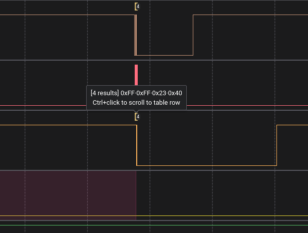
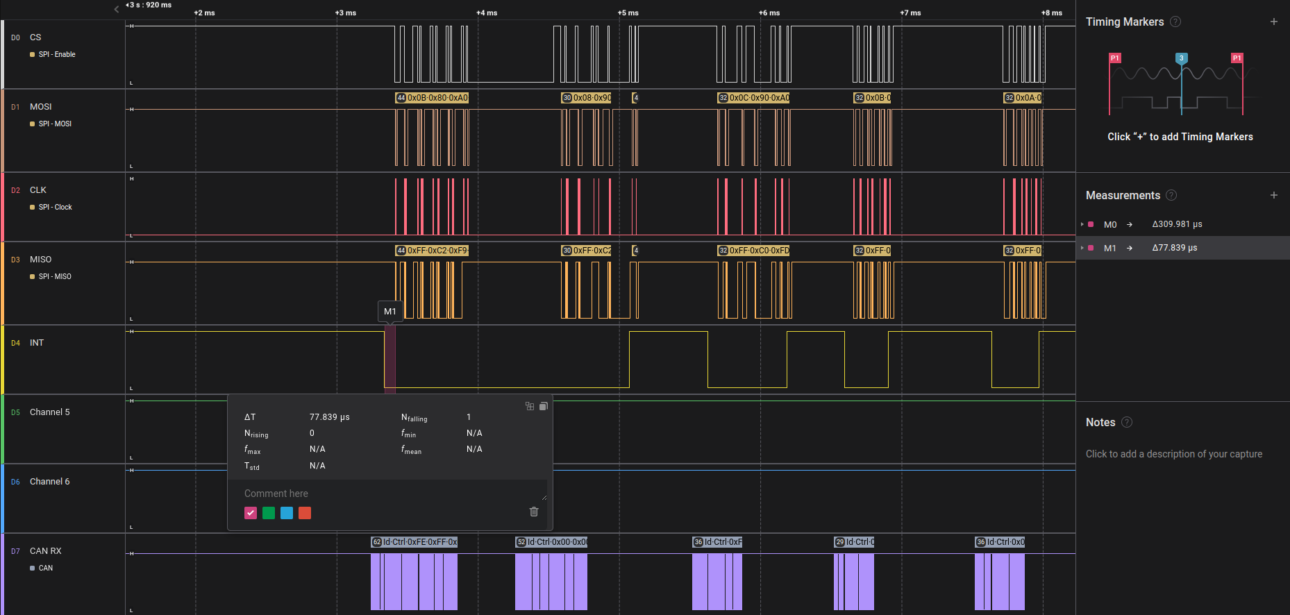
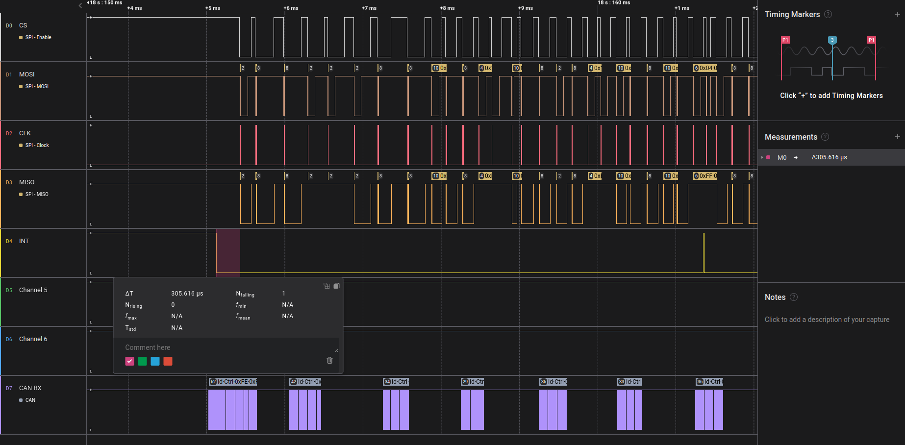
That what i see in logic analyzer on SPI bus between MCP and Radxa:
CAN frequency: 1MHz
SPI frequency: 8MHz


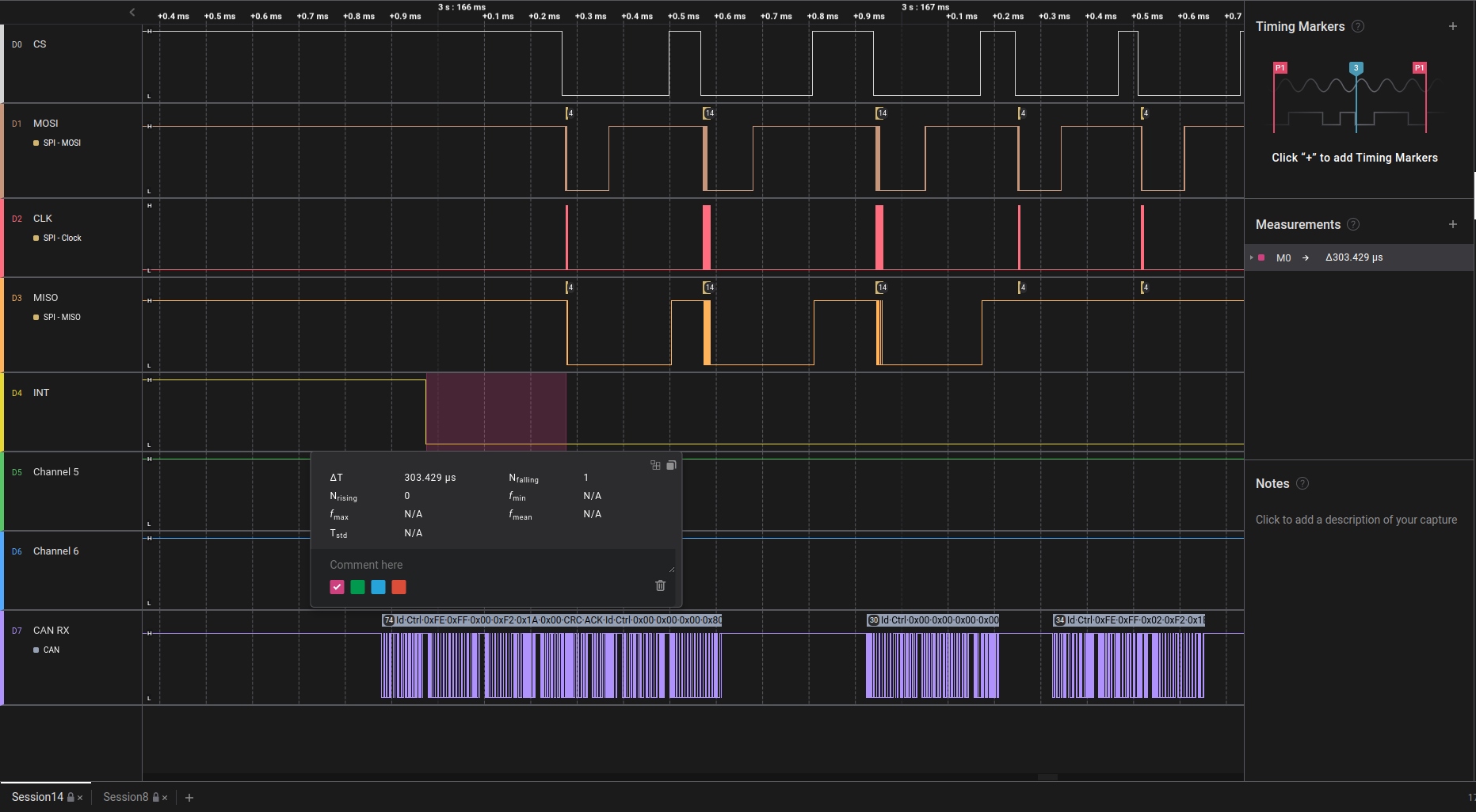
How it can be seen on sreenshot above, there is delay between getting INTerrupt from MCP2515 and
pulling CS pin down. The delay is about 300 µs. During this time MCP2515 gets almost 4 CAN messages. But there is only 2 receive buffers to store messages in MCP2515.
MCP says me:
Screenshot_20230605_140439
That means buffers overflow)

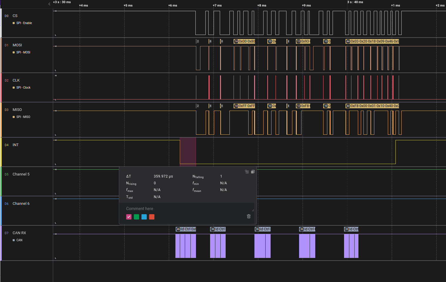
I have RPI CM3+ with the same connection scheme. It works ok:


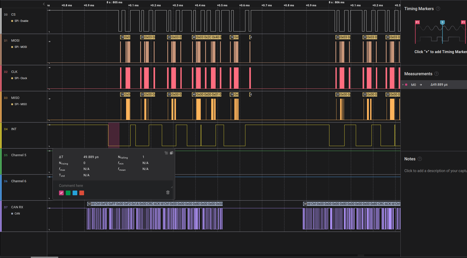
The delay is only 50 µs and all CAN messages are received in the correct order without loss

I thought it might be the MCP driver, but on the RPi+ it’s the same driver, at least it hasn’t changed since 2018 ))

What can be wrong?
Help :upside_down_face:

Here is the original file for the overlay. Are you able to find the source file for Raspberry Pi overlay and compare the configuration?

I tried to assemble overlays from attached repo but get the error:

cpp -x assembler-with-cpp -E -I "/usr/src/linux-headers-4.19.193-3-rk356x/include" -I "/usr/lib/modules/4.19.193-3-rk356x/build/include" "arch/arm64/boot/dts/amlogic/overlays/meson-g12-gpio-poweroff.dts" "arch/arm64/boot/dts/amlogic/overlays/meson-g12-gpio-poweroff.dtbo.tmp"
arch/arm64/boot/dts/amlogic/overlays/meson-g12-gpio-poweroff.dts:5:10: fatal error: dt-bindings/gpio/meson-g12a-gpio.h: No such file or directory
    5 | #include <dt-bindings/gpio/meson-g12a-gpio.h>
      |          ^~~~~~~~~~~~~~~~~~~~~~~~~~~~~~~~~~~~
compilation terminated.
make: *** [Makefile:23: arch/arm64/boot/dts/amlogic/overlays/meson-g12-gpio-poweroff.dtbo] Error 1

I cloned repo to radxa and execute make.
Maybe I did something wrong?

I assumed that to compile the overlays need device tree source files for current image, unfortunately i don’t have it in .dts format ((
But overall .dts of MCP(which you attached) looks like my decompiled .dtbo above ))

Here is the RPi overlay for MCP which i decompiled from .dtbo because don’t have source code either:

/dts-v1/;

/ {
        compatible = "brcm,bcm2835", "brcm,bcm2836", "brcm,bcm2708", "brcm,bcm2709";

        fragment@0 {
                target = <0xffffffff>;

                __overlay__ {
                        status = "okay";
                };
        };

        fragment@1 {
                target = <0xffffffff>;

                __overlay__ {
                        status = "disabled";
                };
        };

        fragment@2 {
                target = <0xffffffff>;

                __overlay__ {

                        can0_pins {
                                brcm,pins = <0x19>;
                                brcm,function = <0x0>;
                                phandle = <0x1>;
                        };
                };
        };

        fragment@3 {
                target-path = "/clocks";

                __overlay__ {

                        can0_osc {
                                compatible = "fixed-clock";
                                #clock-cells = <0x0>;
                                clock-frequency = <0xf42400>;
                                phandle = <0x2>;
                        };
                };
        };

        fragment@4 {
                target = <0xffffffff>;

                __overlay__ {
                        #address-cells = <0x1>;
                        #size-cells = <0x0>;

                        mcp2515@0 {
                                reg = <0x0>;
                                compatible = "microchip,mcp2515";
                                pinctrl-names = "default";
                                pinctrl-0 = <0x1>;
                                spi-max-frequency = <0x989680>;
                                interrupt-parent = <0xffffffff>;
                                interrupts = <0x19 0x8>;
                                clocks = <0x2>;
                                phandle = <0x3>;
                        };
                };
        };

        __overrides__ {
                oscillator = [00 00 00 02 63 6c 6f 63 6b 2d 66 72 65 71 75 65 6e 63 79 3a 30 00];
                spimaxfrequency = <0x3 0x7370692d 0x6d61782d 0x66726571 0x75656e63 0x793a3000>;
                interrupt = [00 00 00 01 62 72 63 6d 2c 70 69 6e 73 3a 30 00 00 00 00 03 69 6e 74 65 72 72 75 70 74 73 3a 30 00];
        };

        __symbols__ {
                can0_pins = "/fragment@2/__overlay__/can0_pins";
                can0_osc = "/fragment@3/__overlay__/can0_osc";
                can0 = "/fragment@4/__overlay__/mcp2515@0";
        };

        __fixups__ {
                spi0 = "/fragment@0:target:0", "/fragment@4:target:0";
                spidev0 = "/fragment@1:target:0";
                gpio = "/fragment@2:target:0", "/fragment@4/__overlay__/mcp2515@0:interrupt-parent:0";
        };

        __local_fixups__ {

                fragment@4 {

                        __overlay__ {

                                mcp2515@0 {
                                        pinctrl-0 = <0x0>;
                                        clocks = <0x0>;
                                };
                        };
                };

                __overrides__ {
                        oscillator = <0x0>;
                        spimaxfrequency = <0x0>;
                        interrupt = <0x0 0x10>;
                };
        };
};

I don’t think that overlay is culprit because it works well in general )) But the speed of handling interrupt is so slow.

Maybe the problem with delay is relate with wrong interrupt-parrent in overlay or interrupts priority in the system …

The make command without any arguments is intended to be run with a relatively recent upstream Linux kernel header. You can run make arch/arm64/boot/dts/rockchip/overlays/rk3568-spi3-m1-cs0-mcp2515.dtbo instead.

Thanks for the tip but I getting error again ((

radxa@radxa-cm3-sodimm-io:~/git/overlays$ make arch/arm64/boot/dts/rockchip/overlays/rk3568-spi3-m1-cs0-mcp2515.dtbo
cpp -x assembler-with-cpp -E -I "/usr/src/linux-headers-4.19.193-3-rk356x/include" -I "/usr/lib/modules/4.19.193-3-rk356x/build/include" "arch/arm64/boot/dts/rockchip/overlays/rk3568-spi3-m1-cs0-mcp2515.dts" "arch/arm64/boot/dts/rockchip/overlays/rk3568-spi3-m1-cs0-mcp2515.dtbo.tmp"
dtc -q -@ -I dts -O dtb -o "arch/arm64/boot/dts/rockchip/overlays/rk3568-spi3-m1-cs0-mcp2515.dtbo" "arch/arm64/boot/dts/rockchip/overlays/rk3568-spi3-m1-cs0-mcp2515.dtbo.tmp"
Error: /usr/include/stdc-predef.h:0.36-37 syntax error
FATAL ERROR: Unable to parse input tree
make: *** [Makefile:24: arch/arm64/boot/dts/rockchip/overlays/rk3568-spi3-m1-cs0-mcp2515.dtbo] Error 1

This issue is fixed in the latest commit.

Thanks for fast fix!
I made some changes to dts:

  1. interrupts to <RK_PC0 IRQ_TYPE_EDGE_FALLING>
  2. interrupt-parent to <&gpio4>
  3. clock-frequency of oscillator to <20000000>
  4. pinctrl-0 to <&spi3m0_cs0 &spi3m0_pins>
  5. pinctrl-1 to <&spi3m0_cs0 &spi3m0_pins_hs>

Now it looks:

/dts-v1/;
/plugin/;

#include <dt-bindings/gpio/gpio.h>
#include <dt-bindings/pinctrl/rockchip.h>
#include <dt-bindings/interrupt-controller/irq.h>

/ {

        metadata {
                title = "Enable MCP2515 on SPI3-M1 CS0";
                compatible = "radxa,rock-3c";
                category = "misc";
                exclusive = "GPIO4_C2", "GPIO4_C3", "GPIO4_C5", "GPIO4_C6", "GPIO3_C1";
                description = "Enable MCP2515 on SPI3-M1 CS0 with 12 MHz Crystal Oscillator.\nINT=22";
        };

        fragment@0 {
                target = <&pinctrl>;

                __overlay__ {
                        mcp2515_int_pin {
                                mcp2515_int_pin: mcp2515_int_pin {
                                        rockchip,pins = <3 RK_PC1 RK_FUNC_GPIO &pcfg_pull_none>;
                                };
                        };
                };
        };

        fragment@1 {
                target-path = "/";

                __overlay__ {
                        can_mcp2515_osc: can-mcp2515-osc {
                                compatible = "fixed-clock";
                                clock-frequency = <20000000>;
                                #clock-cells = <0>;
                        };
                };
        };

        fragment@2 {
                target = <&spi3>;

                __overlay__ {
                        status = "okay";
                        max-freq = <10000000>;
                        #address-cells = <1>;
                        #size-cells = <0>;
                        pinctrl-names = "default", "high_speed";
                        pinctrl-0 = <&spi3m0_cs0 &spi3m0_pins>;
                        pinctrl-1 = <&spi3m0_cs0 &spi3m0_pins_hs>;

                        can_mcp2515: can-mcp2515@0 {
                                status = "okay";
                                compatible = "microchip,mcp2515";
                                reg = <0>;
                                interrupt-parent = <&gpio4>;
                                interrupts = <RK_PC0 IRQ_TYPE_EDGE_FALLING>;
                                spi-max-frequency = <10000000>;
                                clocks = <&can_mcp2515_osc>;
                                vdd-supply = <&vcc3v3_sys>;
                                xceiver-supply = <&vcc3v3_sys>;
                                pinctrl-names = "default";
                                pinctrl-0 = <&mcp2515_int_pin>;
                        };
                };
        };
};

But I see the same problem((

And I didn’t understand why mcp2515_int_pin is need. It doesn’t affect anything. Can you explain to me if you know?

I noticed that there isn’t big delay in the first messages:


But after receiving several messages I see that time between receiving interrupt from MCP2515 and pulling CS pin down is about 300 µs again:

This is /proc/interrupts and you can see that mcp251x has a lowest priority:

radxa@radxa-cm3-sodimm-io:~$ cat /proc/interrupts 
           CPU0       CPU1       CPU2       CPU3       
  1:          0          0          0          0     GICv3  25 Level     vgic
  4:          0          0          0          0     GICv3  27 Level     kvm guest timer
  5:      24776      34185      32612      21810     GICv3  26 Level     arch_timer
  6:      35890      55666      39402      25402     GICv3 141 Level     rk_timer
  7:          0          0          0          0     GICv3 260 Level     arm-pmu
  8:          0          0          0          0     GICv3 261 Level     arm-pmu
  9:          0          0          0          0     GICv3 262 Level     arm-pmu
 10:          0          0          0          0     GICv3 263 Level     arm-pmu
 15:       7995          0          0          0     GICv3  78 Level     fdd40000.i2c
 16:       8340          0          0          0     GICv3  71 Level     fde60000.gpu
 17:          4          0          0          0     GICv3  73 Level     fde60000.gpu
 18:       7494          0          0          0     GICv3  72 Level     fde60000.gpu
 19:          0          0          0          0     GICv3 171 Level     fdea0400.vdpu
 20:          0          0          0          0     GICv3 170 Level     fdea0800.iommu
 21:          0          0          0          0     GICv3 122 Level     rga
 22:          0          0          0          0     GICv3  94 Level     fded0000.jpegd
 23:          0          0          0          0     GICv3  93 Level     fded0480.iommu
 24:          0          0          0          0     GICv3  96 Level     fdee0000.vepu
 25:          0          0          0          0     GICv3  95 Level     fdee0800.iommu
 26:          0          0          0          0     GICv3  88 Level     fdef0800.iommu, fdef0000.iep
 27:          0          0          0          0     GICv3 172 Level     fdf40000.rkvenc
 28:          0          0          0          0     GICv3 173 Level     fdf40f00.iommu
 29:          0          0          0          0     GICv3 174 Level     fdf40f00.iommu
 30:          0          0          0          0     GICv3 123 Level     fdf80200.rkvdec
 31:          0          0          0          0     GICv3 124 Level     fdf80800.iommu
 32:          0          0          0          0     GICv3 178 Level     fdfe0800.iommu
 33:          0          0          0          0     GICv3  89 Level     rkisp_hw
 34:          0          0          0          0     GICv3  90 Level     rkisp_hw
 35:          0          0          0          0     GICv3  92 Level     rkisp_hw
 36:          0          0          0          0     GICv3  91 Level     fdff1a00.iommu
 37:          0          0          0          0     GICv3 180 Level     fe043e00.iommu, fe040000.vop
 38:          0          0          0          0     GICv3  77 Level     fe0a0000.hdmi, dw-hdmi-cec
 39:         42          0          0          0     GICv3 130 Level     dw-mci
 40:     184984          0          0          0     GICv3 131 Level     dw-mci
 41:          0          0          0          0     GICv3 133 Level     rksfc
 42:      17791          0          0          0     GICv3  51 Level     mmc0
 45:          0          0          0          0     GICv3  46 Level     fe530000.dmac
 46:          0          0          0          0     GICv3  45 Level     fe530000.dmac
 47:        402          0          0          0     GICv3  48 Level     fe550000.dmac
 48:          0          0          0          0     GICv3  47 Level     fe550000.dmac
 49:         10          0          0          0     GICv3  80 Level     fe5b0000.i2c
 51:      15568          0          0          0     GICv3 138 Level     fe640000.spi
 52:          2          0          0          0     GICv3 149 Level     ttyS1
 53:          2          0          0          0     GICv3 150 Level     ttyS2
 54:          0          0          0          0     GICv3 147 Level     rockchip_thermal
 55:          0          0          0          0     GICv3 125 Level     fe720000.saradc
 56:          0          0          0          0     GICv3 167 Level     rockchip_usb2phy
 62:          0          0          0          0     gpio0   3 Level     rk817
 63:          0          0          0          0     rk817   0 Edge      rk805_pwrkey_fall
 64:          0          0          0          0     rk817   1 Edge      rk805_pwrkey_rise
 68:          0          0          0          0     rk817   5 Edge      RTC alarm
 87:          0          0          0          0     GICv3 201 Level     xhci-hcd:usb1, dwc3
 88:      14140          0          0          0     gpio2  17 Level     brcmf_oob_intr
 89:       1783          0          0          0     gpio4  16 Edge      mcp251x
IPI0:     23343     110749      39594      58457       Rescheduling interrupts
IPI1:       289        361        392        255       Function call interrupts
IPI2:         0          0          0          0       CPU stop interrupts
IPI3:         0          0          0          0       CPU stop (for crash dump) interrupts
IPI4:     10906      14506      13871      12467       Timer broadcast interrupts
IPI5:      4143       3271      15426       2557       IRQ work interrupts
IPI6:         0          0          0          0       CPU wake-up interrupts
Err:          0

Could this be related with my problem?

is the interrupt pin on the module:

So you definitely want to have this configured and connected.

Hmm
According to linux docs interrupts should contain IRQ line and interrupt type. I wrote that I changed it, in my previous reply.

My interrupt pin is GPIO4_CO, respectively in interrupt-parent I specify interrupt-controller i. e. gpio4 and in interrupts: C0(16 pin of gpio4 group), interrupt condition IRQ_TYPE_EDGE_FALLING. It works right.

Also I tried to change mcp2515_int_pin to random GPIOs, but it didn’t take any affect on SPI functionality.

I’m following your post with interest to gain insight.

So I’m just throwing this in as a suggestion as I have used this in the past for a different spi driver, but I have no validation that it actually does anything special. But my interrupt pin was working.

So within

can_mcp2515: can-mcp2515@0 { ... }

You could try adding

    gpio-controller;
    interrupt-controller;
    #gpio-cells = <2>;
    #interrupt-cells = <2>;
    #address-cells = <0>;

Thanks for wish to help, but it didn’t work for me :frowning:

Error: arch/arm64/boot/dts/rockchip/overlays/rk3568-spi3-m1-cs0-mcp2515.dts:61.25-26 syntax error
FATAL ERROR: Unable to parse input tree
make: *** [Makefile:24: arch/arm64/boot/dts/rockchip/overlays/rk3568-spi3-m1-cs0-mcp2515.dtbo] Error 1

then i started to speculate and left only this:

gpio-controller;
interrupt-controller;

It compiled, but didn’t have any effect for SPI.

I see that you received a “FATAL ERROR: Unable to parse input tree” message. Usually that is suggesting a syntax error and relates to pin-control or interrupt-control. I even found that the compiler complains about silly things, so it could be down to this…

[quote="Vshunya, post:7, topic:17008"]
mcp2515_int_pin: mcp2515_int_pin
[/quote]

I know I had a similar and changed the above to something like this "mcp2515_int_pin: mcp2515-int-pin" and surprise surprise it worked with the #gpio-cells = <2>; #interrupt-cells = <2>;  #address-cells = <0>;.

Sorry for long time reply :slight_smile:

If i understood you correctly I need to do this:

  1. Include all from your first reply to can_mcp2515
  2. Specify correct interrupt pin in mcp2515_int_pin
/dts-v1/;
/plugin/;

#include <dt-bindings/gpio/gpio.h>
#include <dt-bindings/pinctrl/rockchip.h>
#include <dt-bindings/interrupt-controller/irq.h>

/ {

        metadata {
                title = "Enable MCP2515 on SPI3-M1 CS0";
                compatible = "radxa,rock-3c";
                category = "misc";
                exclusive = "GPIO4_C2", "GPIO4_C3", "GPIO4_C5", "GPIO4_C6", "GPIO3_C1";
                description = "Enable MCP2515 on SPI3-M1 CS0 with 12 MHz Crystal Oscillator.\nINT=22";
        };

        fragment@0 {
                target = <&pinctrl>;

                __overlay__ {
                        mcp2515_int_pin {
                                mcp2515_int_pin: mcp2515_int_pin {
                                        rockchip,pins = <4 RK_PC0 RK_FUNC_GPIO &pcfg_pull_none>;
                                };
                        };
                };
        };

        fragment@1 {
                target-path = "/";

                __overlay__ {
                        can_mcp2515_osc: can-mcp2515-osc {
                                compatible = "fixed-clock";
                                clock-frequency = <20000000>;
                                #clock-cells = <0>;
                        };
                };
        };

        fragment@2 {
                target = <&spi3>;

                __overlay__ {
                        status = "okay";
                        max-freq = <10000000>;
                        #address-cells = <1>;
                        #size-cells = <0>;
                        pinctrl-names = "default", "high_speed";
                        pinctrl-0 = <&spi3m0_cs0 &spi3m0_pins>;
                        pinctrl-1 = <&spi3m0_cs0 &spi3m0_pins_hs>;

                        can_mcp2515: can-mcp2515@0 {
                                status = "okay";
                                compatible = "microchip,mcp2515";
                                reg = <0>;
                                interrupt-parent = <&gpio4>;
                                interrupts = <RK_PC0 IRQ_TYPE_EDGE_FALLING>;
                                gpio-controller;
                                interrupt-controller;
                                #gpio-cells = <2>;
                                #interrupt-cells = <2>;
                                #address-cells = <0>;
                                spi-max-frequency = <10000000>;
                                clocks = <&can_mcp2515_osc>;
                                vdd-supply = <&vcc3v3_sys>;
                                xceiver-supply = <&vcc3v3_sys>;
                                pinctrl-names = "default";
                                pinctrl-0 = <&mcp2515_int_pin>;
                        };
                };
        };
};

Now it assemble, but …
The delay is still here ((

What Linux kernel are you using for the Radxa CM3S - your comments suggest that you are using a new release. Does this differ from the RPI CM3+.

As there is a delay in the CS pin changing state, maybe there is a lookup table somewhere to get the default CS pin that is delaying matters (pure guess).

You could test this theory using the overlay. E.g. to hard code in the default you can use
cs-gpios = <0>,<0>;

As in…

       fragment@2 {
                target = <&spi3>;

                __overlay__ {
                        status = "okay";
                        max-freq = <10000000>;
                        #address-cells = <1>;
                        #size-cells = <0>;
                        pinctrl-names = "default", "high_speed";
                        pinctrl-0 = <&spi3m0_cs0 &spi3m0_pins>;
                        pinctrl-1 = <&spi3m0_cs0 &spi3m0_pins_hs>;
                        cs-gpios = <0>,<0>;         // specifying that CS0 and CS1 are default

                        can_mcp2515: can-mcp2515@0 { ... }

Or if you want to specify your own GPIO pin for CS0 then use: cs-gpios = <&gpio4 1 0>; // i.e. GPIO4_A1 etc.

Reference: https://www.kernel.org/doc/Documentation/devicetree/bindings/spi/spi-gpio.txt

PS. if “cs-gpios” throws an error with compile use “cs-gpio”

Hello Vshunya,

I am currently working on a project involving the MCP2515 module for CAN communication between my Rock5B board and an Arduino. I have successfully enabled create the .dtbo file that I have copy and paste in the dtbo folder. I am working on Debian 11.

Could you guide me on how to load the MCP2515 overlay specifically for the Rock5B? Additionally, I would appreciate any insights on the subsequent steps required after enabling the overlay to ensure the MCP2515 module works correctly.

Thank you in advance for your assistance and valuable suggestions!

RPi has kernel version 4.14.50
Radxa - 4.19.193 (b24)

Thanks
Everything were compiled with cs-gpios, but had no effect on SPI ((

CS/CE, according docs, specifying in reg field. And it’s strange, because it’s not clear how to specify no standard CS/CE to the SPI3 through req field, for example GPIO3_B3.

Hello ))

I had a deal only with CM3S and don’t know how it work for Rock5B.
But I can tell how I’m doing:

  1. Create .dtbo
    You can use already ready overlay if pin-out suits you. Or you if you don’t have sources(.dts files), You can decompile it:
dtc -I dtb -O dts overlay_name.dtbo -o overlay_name.dts

Make some changes in .dts file and compile back:

dtc -I dts -O dtb overlay_name.dts -o overlay_name.dtbo

but it’s better to use sources. @RadxaYuntian left a link to it in the reply above.

  1. After it i just copy created overlay to /boot/dtbo or it can be in /boot/dtbs/4.19.193-215-rockchip-g2657e70400fc/rockchip/overlay or something like that

  2. Next I edited extLinux.conf in my case it in /boot/extLinux, min looks like this:

## /boot/extlinux/extlinux.conf
##
## IMPORTANT WARNING
##
## The configuration of this file is generated automatically.
## Do not edit this file manually, use: u-boot-update

default l0
menu title U-Boot menu
prompt 0
timeout 10


label l0
        menu label Debian GNU/Linux 11 (bullseye) 4.19.193-3-rk356x
        linux /boot/vmlinuz-4.19.193-3-rk356x
        initrd /boot/initrd.img-4.19.193-3-rk356x
        fdtdir /usr/lib/linux-image-4.19.193-3-rk356x/
        fdtoverlays /boot/dtbo/rk3568-fiq-debugger-uart9m2.dtbo /boot/dtbo/radxa-cm3s-io-csi0-rpi-camera-v2.dtbo /boot/dtbo/rk3568-spi3-m1-cs0-mcp2515.dtbo /boot/dtbo/rk3568-uart2-m0.dtbo
        append root=UUID=2145034c-4176-4996-b2c4-e0960f0f51e6 rw loglevel=4 console=tty0 console=ttyAML0,115200n8 console=ttyS2,1500000n8 console=ttyFIQ0,1500000n8 coherent_pool=2M irqchip.gicv3_pseudo_nmi=0 quiet splash plymouth.ignore-serial-consoles

label l0r
        menu label Debian GNU/Linux 11 (bullseye) 4.19.193-3-rk356x (rescue target)
        linux /boot/vmlinuz-4.19.193-3-rk356x
        initrd /boot/initrd.img-4.19.193-3-rk356x
        fdtdir /usr/lib/linux-image-4.19.193-3-rk356x/
        fdtoverlays /boot/dtbo/rk3568-fiq-debugger-uart9m2.dtbo /boot/dtbo/radxa-cm3s-io-csi0-rpi-camera-v2.dtbo /boot/dtbo/rk3568-spi3-m1-cs0-mcp2515.dtbo /boot/dtbo/rk3568-uart2-m0.dtbo
        append root=UUID=2145034c-4176-4996-b2c4-e0960f0f51e6 rw loglevel=4 console=tty0 console=ttyAML0,115200n8 console=ttyS2,1500000n8 console=ttyFIQ0,1500000n8 coherent_pool=2M irqchip.gicv3_pseudo_nmi=0 splash plymouth.ignore-serial-consoles single

I understand, that it says “do not edit” :grinning: buuut …
It’s the only one way that it works for me, because the recommended rsetup utility didn’t work in my case

So, you need to specify the way to your overlays in fdtoverlays line for your kernel through a space

  1. Save file and reboot))
  2. After reboot check loaded modules, if all was done correct, you will see
radxa@radxa-cm3-sodimm-io:~$ lsmod
Module                  Size  Used by
.......
mcp251x                20480  0
.......

Or something like that.

  1. Start CAN, but replace bitrate to your own.
ip link set dev can0 up type can bitrate 1000000
  1. Check whether CAN interface was up, If previous steps went well, than we will see this:
radxa@radxa-cm3-sodimm-io:~$ ip addr
....
2: can0: <NOARP,UP,LOWER_UP,ECHO> mtu 16 qdisc pfifo_fast state UP group default qlen 10
    link/can 
....

or ifconfig

radxa@radxa-cm3-sodimm-io:~$ sudo ifconfig
can0: flags=193<UP,RUNNING,NOARP>  mtu 16
        unspec 00-00-00-00-00-00-00-00-00-00-00-00-00-00-00-00  txqueuelen 10  (UNSPEC)
        RX packets 3061  bytes 22070 (21.5 KiB)
        RX errors 626  dropped 0  overruns 0  frame 626
        TX packets 6  bytes 38 (38.0 B)
  1. Download can-utils for reading CAN frames:
sudo apt install can-utils

And then listen to the interface:

candump can0

Just save your overlay under /boot/dtbo folder and run sudo u-boot-update. It will automatically add every *.dtbo file to extlinux.conf.

1 Like

Hey Vshunya and RadxaYuntian,

Just wanted to send a quick shoutout to express my gratitude for the support you’ve given me with my board, the ROCK5B.

I followed all your instructions, editong the extlinux.conf file or running “sudo u-boot-update,” but unfortunately, I’m still unable to get the MCP251x module loaded.

I’m reaching out to see if you have any additional suggestions or troubleshooting tips to help me crack this puzzle.

Thanks a million for all your help and patience. Looking forward to hearing back from you soon.

Can you point out which step you are stuck on?