Argh! I’m disgusted! I’ve received my DS1338 chips and they were still not detected. After looking closer at the schematic, I noticed that I was confused by the pins naming: I2C0_SDA_M1 vs I2C1_SDA_M0, so no, the RTC and EEPROM are not on the same bus, so they don’t conflict. In fact I2C0 was disabled in the DTS, reason why I didn’t find it suspicious to have the two on what I believed was the same bus.
After enabling I2C0 in the DTS with this:
--- a/arch/arm64/boot/dts/rockchip/rk3528-radxa-e20c.dts
+++ b/arch/arm64/boot/dts/rockchip/rk3528-radxa-e20c.dts
@@ -18,6 +18,7 @@

        aliases {
                ethernet0 = &gmac1;
+               i2c0 = &i2c0;
                i2c1 = &i2c1;
                mmc0 = &sdhci;
                mmc1 = &sdmmc;
@@ -198,6 +199,12 @@
        status = "okay";
 };

+&i2c0 {
+       pinctrl-names = "default";
+       pinctrl-0 = <&i2c0m1_xfer>;
+       status = "okay";
+};
+
 &i2c1 {
        pinctrl-names = "default";
        pinctrl-0 = <&i2c1m0_xfer>;
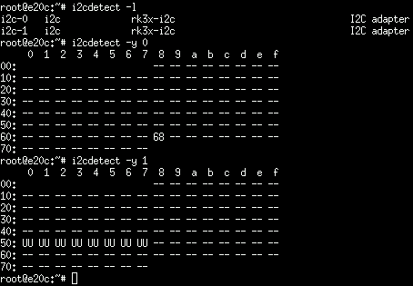
Then my chip is properly detected at 0x68:
Also, I found that DS1338, while interesting (and sucking very low power), requires a distinct Vbat pin that matches the /INT pin of the HYM8563. The copper trace passes very close to the battery diode so it should be reasonably easy to derive it from there, but I’d rather reinstall the 8563 to match the DTS and avoid cutting tracks. Also, one nice thing about DS1338 is that it includes its own capacitors for the Xtal, so it could be more usable for hand soldering. I’ll try without, as often the capacitance of the xtal is within tolerance margin and works, and I’ll see, because quite frankly, soldering 0201, even with a microscope, is a pain, they stick to the soldering tip, and the even fine tweezers are too large to hold them while soldering. Hot air is not easy due to all components in the vicinity.
Going back to replacing that chip now…
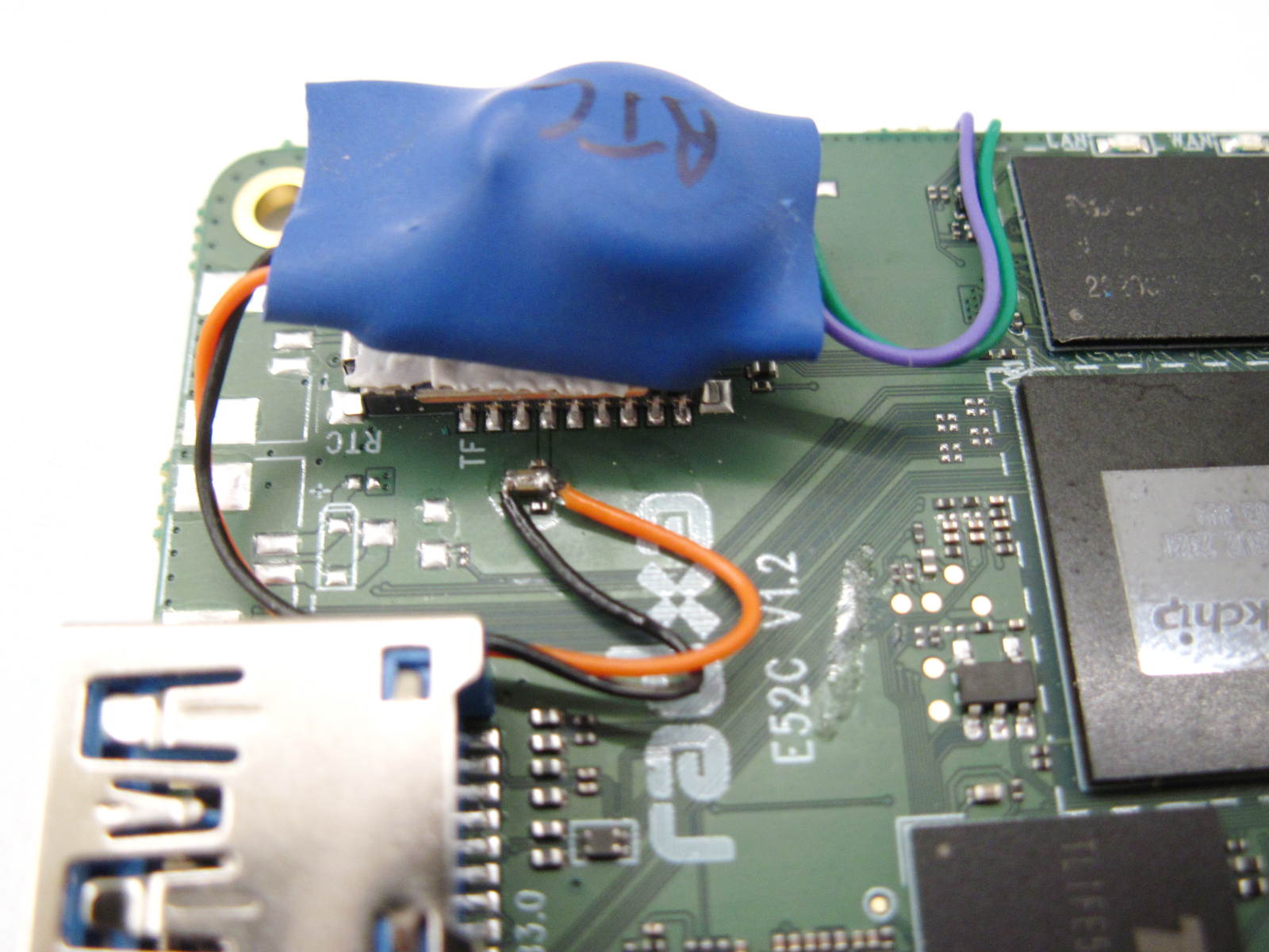
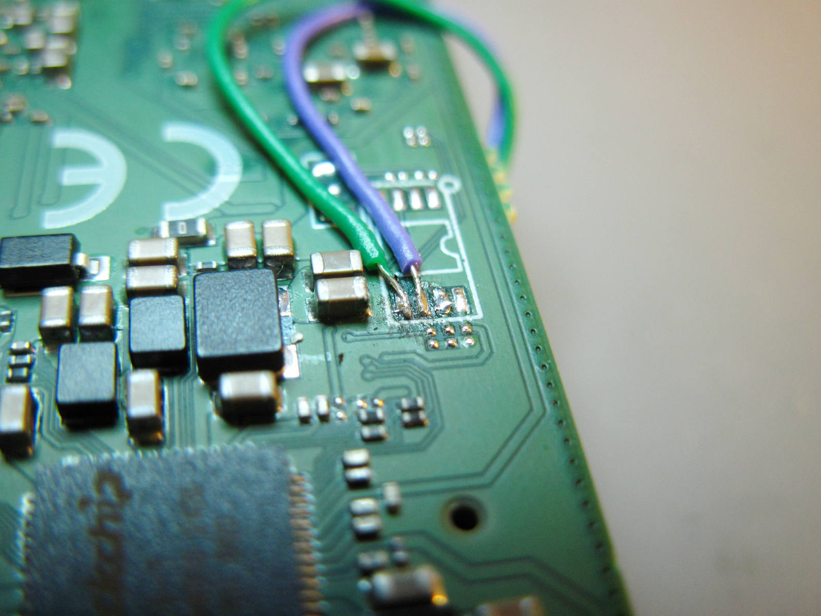
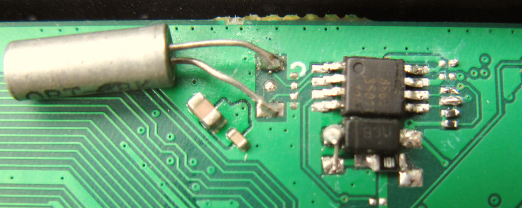
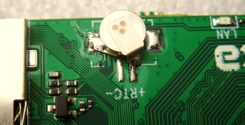
Edit: HYM8563 now soldered and working like a charm. I only added the 8563, the 32kHz XTAL (on the left), a low dropout diode between 3v3 and Vcc (below the chip), a 100 ohm resistor to charge the supercap without pulling too hard from the diode (below the diode), and the supercap on the other side, it fits fine on the RTC connector’s pads. I also had to solder two jumpers for SDA/SCL. This is difficult to do at this scale (0.3mm wide by 0.6mm long, the chip is 3mm wide to give an idea of the scale) because the solder wire tends to make big balls when fusing, and to stick to the soldering tip. Anyway I was happy not to have to solder any caps nor the pull up diodes. The chip was pre-positionned using hot air and finished with the soldering iron and flux under a microscope (it’s slightly rotated because I couldn’t use the microscope with the hot air). Here are photos of the bottom (chip) and top (supercap):
I wouldn’t do that every day but now I’m happy that the device is hardware-complete, and I’ll soon be able to use it.
Oh and BTW regarding the supercap, I used these ones: https://www.aliexpress.com/item/1005006869819627.html . That’s 0.07F at $0.16/pc which I estimated should last roughly a month. It avoids the lithium issues and even saves the RTC connector. IMHO it could even be smaller (0.033) since such machines are not supposed to deal with long outages while keeping their clock. @hipboi you might be interested in seeing it at scale here to get an idea of how it fits on the board. I think that for such devices, anything lasting at least a week (~0.022F) would be suited, and then only the lowest price matters.

 (U17 IIRC).