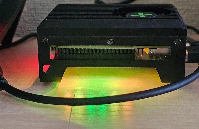
Hoping @makerbymistake or anyone else can help me out - I’ve been working on getting the Pimoroni Blinkt! up and running on the Radxa X4, with a view to sending CPU Load and Temperature data to the RP2040 and illuminating the LEDs as appropriate.
I have the LED code up and running in both MicroPython and CircuitPython and it operates the LEDs correctly (tested by manually entering data in the code). However, I cannot figure out how to get the live CPU data communicated from Windows to the RP2040 (first time doing this). So it’s the serial communication part of the code below I need help with.
I’m using a Powershell script to get the data (haven’t tried doing this using Python on Windows, as I’m hoping the Powershell will work out). Below is my code - I really need help getting the comms over serial working. I’ve tried the CircuitPython usb_cdc code on the page @makerbymistake linked above and got an error message about ‘in.waiting’, so went with the code below for the moment. If I’m going about the comms in the wrong way, or this is not possible with Powershell, please let me know!
CircuitPython Script (also tried using MicroPython)
CircuitPython script to receive CPU data over serial and illuminate LEDs appropriately:
import array
import time
import board
import busio
import adafruit_dotstar as dotstar

# Set up DotStar for Blinkt!
dots = dotstar.DotStar(board.GP27, board.GP22, 8, brightness=0.1, auto_write=True)

# Initialize UART for CircuitPython
uart = busio.UART(board.GP0, board.GP1, baudrate=115200)

# Set up RGB color values in arrays - integers for [R, G, B]
COLORS = {
"RED": array.array('i', [255, 0, 0]),
"GREEN": array.array('i', [0, 255, 0]),
"BLUE": array.array('i', [0, 0, 255]),
"YELLOW": array.array('i', [255, 255, 0]),
"ORANGE": array.array('i', [255, 150, 0]),
"WHITE": array.array('i', [255, 255, 255]),
}

# Set up LED color configurations for each temperature range
TEMP_COLORS = [
    [COLORS["BLUE"], COLORS["GREEN"], COLORS["YELLOW"], COLORS["ORANGE"]],
    [COLORS["GREEN"], COLORS["YELLOW"], COLORS["ORANGE"], COLORS["RED"]],
    [COLORS["YELLOW"], COLORS["ORANGE"], COLORS["RED"], COLORS["RED"]],
    [COLORS["ORANGE"], COLORS["RED"], COLORS["RED"], COLORS["RED"]],
    [COLORS["RED"], COLORS["RED"], COLORS["RED"], COLORS["RED"]],
    [COLORS["WHITE"], COLORS["WHITE"], COLORS["WHITE"], COLORS["WHITE"]],
]

# Set Brightness levels based on CPU load
BRIGHTNESS_LEVELS = [
    (0.1, [3, 4]),
    (0.1, [3, 4]),
    (0.1, [2, 3, 4, 5]),
    (0.1, [1, 2, 3, 4, 5, 6]),
    (0.2, range(8)),
]

def set_temp_colors(temp):
    if temp <= 40:
        leds = TEMP_COLORS[0]
    elif temp <= 50:
        leds = TEMP_COLORS[1]
    elif temp <= 60:
        leds = TEMP_COLORS[2]
    elif temp <= 70:
        leds = TEMP_COLORS[3]
    elif temp <= 80:
        leds = TEMP_COLORS[4]
    else:
        leds = TEMP_COLORS[5]
    return leds

def set_led_brightness(load, leds):
    if load < 6:
        brightness, active_leds = BRIGHTNESS_LEVELS[0]
    elif load <= 25:
        brightness, active_leds = BRIGHTNESS_LEVELS[1]
    elif load <= 50:
        brightness, active_leds = BRIGHTNESS_LEVELS[2]
    elif load <= 75:
        brightness, active_leds = BRIGHTNESS_LEVELS[3]
    else:
        brightness, active_leds = BRIGHTNESS_LEVELS[4]

    led_pairs = {3: leds[0], 4: leds[0], 2: leds[1], 5: leds[1],
                 1: leds[2], 6: leds[2], 0: leds[3], 7: leds[3]}

    for i in range(len(dots)):
        if i in active_leds:
            color = led_pairs[i]
            dots[i] = (color[0], color[1], color[2])
            dots.brightness = brightness
        else:
            dots[i] = (0, 0, 0)

def turn_off_all_leds():
    for i in range(len(dots)):
        dots[i] = (0, 0, 0)

# Initialize variables with default values
Hour = 10
CPULoad = 10.0
CPUTemp = 40.0

while True:
    if uart.in_waiting:
        try:
            data = uart.readline().decode('utf-8').strip()
            Hour, CPULoad, CPUTemp = map(float, data.split(','))
            Hour = int(Hour)
        except ValueError:
            continue

    if Hour < 9 or Hour > 20:
        turn_off_all_leds()
        time.sleep(600)
        continue

    leds = set_temp_colors(CPUTemp)
    set_led_brightness(CPULoad, leds)
    time.sleep(1)
Powershell Script
Powershell Script to pull in current hour and then CPU data from LibreHardwareMonitor and send over serial (I’ve tried COM3 with Micropython, and COM4 and COM5 with Circuitpython as both show up in Device Manager). This gets the data and formats it correctly ([hour],[CPULoad],[CPUTemp] - eg ‘11,10.77,45.87’) but getting it across the serial interface is where I’m stuck:
# Load the LibreHardwareMonitor assembly
Add-Type -Path "Q:\Synced\LibreHardwareMonitorLib.dll"

# Initialize Computer object
$computer = New-Object LibreHardwareMonitor.Hardware.Computer
$computer.IsCpuEnabled = $true
$computer.Open()

# Set up the serial port to communicate with the RP2040
$serialPort = New-Object System.IO.Ports.SerialPort "COM4", 115200, 'None', 8, 'One'
$serialPort.Open()

# Loop to continuously output CPU load and temperature
try {
    while ($true) {
        # Get the current hour in 24-hour format
        $currentHour = (Get-Date).Hour

        # Initialize variables for CPU load and temperature
        $cpuLoad = $null
        $cpuTemp = $null

        # Iterate over hardware components
        foreach ($hardware in $computer.Hardware) {
            $hardware.Update()

            if ($hardware.HardwareType -eq [LibreHardwareMonitor.Hardware.HardwareType]::Cpu) {
                foreach ($sensor in $hardware.Sensors) {
				if ($sensor.SensorType -eq [LibreHardwareMonitor.Hardware.SensorType]::Load -and $sensor.Name -eq "CPU Total") {
                    $cpuLoad = $sensor.Value
                }
				elseif ($sensor.SensorType -eq [LibreHardwareMonitor.Hardware.SensorType]::Temperature -and $sensor.Name -eq "CPU Package") {
					$cpuTemp = $sensor.Value
				}
            }
        }
    }

    # Prepare the output string with the hour, CPU load, and temperature
    $output = "{0},{1:N2},{2:N2}" -f $currentHour, $cpuLoad, $cpuTemp  # Hour, Load, Temp

    # For testing purposes, write the output to the Powershell window
    Write-Output $output

    # Send the data to the RP2040 via serial port
    $serialPort.WriteLine($output)

    # Wait for 1 second before the next iteration
    Start-Sleep -Seconds 1
    }
}

finally {
    # Clean up on exit
    $computer.Close()
    $serialPort.Close()
	$serialPort.Dispose()
}

