Folks powering through GPIO pins experience undervoltage issues due to Ohm’s law.
This is cable + contact resistance.
5V at any current higher than 3A is just… BS!
Folks powering through GPIO pins experience undervoltage issues due to Ohm’s law.
This is cable + contact resistance.
5V at any current higher than 3A is just… BS!
As I said in my previous post. Use a 150 mm AWG 22, double it using the pin in parallel and the voltage drop will cause the 5 volts still to be usable with a minimum loss when draining more than 3 A. However I doubt you will get 6A out of it unless you put in in the freezer 
In your previous post you wrote about a ‘current issue’ while it’s a voltage/resistance issue in reality.
And for consumers using SBC it’s crucial to understand this since they think 5V would be 5V regardless of situation and if they just use a beefier power brick with more amps it will work in the end.
As explained already a month ago the GPIO power pins are routed to a buck converter that’s rated 4.5V-26V as such the tolerable voltage drop is just 0.5V.
And of course what you wrote (the shorter and thicker the cable the better, the more contact area the better) is true but only since it reduces cable/contact resistance and helps with the voltage issue everything powered with such low voltages as 5V is affected by.
@tkaiser
Thanks for your explanation. At the end I think we are looking at the issue with different approaches but same meaning. The voltage drop is caused by the resistivity of the conductor, having voltage and resistivity involved, the result is that current plays a role into this situation. However in this context I agree, let’s focus on the voltage drop only so people do not confused.
Absolutely ![]()
But I’m emphasizing on the voltage drop element since that is what people new to the world of 5V powering seem to not understand at all. That it’s not a matter of ‘current too low’ but ‘voltage too low’ (caused by electronics basics).
And us babbling doesn’t change anything wrt the broader problem since those people suffering from undervoltage won’t understand, even don’t want this to hear and seek for authority.
As such Radxa is asked to provide this basic info somewhere we could link to. Though most probably this won’t happen since even Radxa employees recommend this insane 5V @ 6A nonsense… ![]()
haven’t followed the whole discussion, just out of curiosity, does it mean we could provide more than 5v to power the board through GPIO like 12V? or did I miss something?
if correct this would allow to input much more power this way
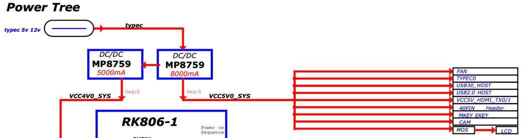
Here’s a link to schematics: https://dl.radxa.com/rock5/5b/docs/hw/radxa_rock_5b_v142_sch.pdf
The normal way of powering (USB-C) results in the provided voltage been transformed by the 1st MP8759 buck converter into 5.15V since this voltage is needed for peripherals. When using anything significantly higher than 5V (like your proposed 12V) at the GPIO header you will likely fry everything attached to USB sockets, HDMI, M.2 sockets and camera connector (all the stuff here on the right):
As such if you’re using your Rock 5B ‘headless’ and only connect power and an Ethernet cable (my usual mode of SBC operation) then higher voltages are fine on the GPIO header otherwise not (but I might miss something so better don’t do this unless you can and actually do read schematics).
The 2nd MP8759 is then used to transform these 5.xV from the 1st MP8759 into 4V that go into the RK806 PMU which then creates all the additional voltages chips and other components need:
And to repeat it a 3rd time in this same thread: MP8759’s input voltage is rated 4.5V-26V as such when powering with 5V the tolerable voltage drop is just 0.5V! With cables that are not ultra short and extra thick, connecting only 2 power pins and just a minor load this will result in your board rebooting occasionally since Ohm’s law!
Considering the yield rate of chip fabrication, the 4.5v to 26v input voltage is not an absolute range.
Some MP8759 may be able to work with a bit lower input voltage and some may need a higher input voltage.
So, it’s possible some user can stably drive the board at 5V/3A sustaining the voltage drop and some could not.
It needs the user to find it out, like adjusting the core voltage to overclock the CPU.
I think it’s possible to provide a bit higher input voltage to the power pin but definitely not starting with 12V. (maybe 100mV at each step?)
Before doing that, you may want:
Good luck.
Letting aside all issues related to double-powering via GPIO and USB-C, certainly a lot of care should be taken when powering via GPIO. We forum users can and should work on filling all knowledge gaps.
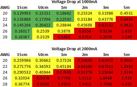
@tkaiser, where did you take the table values from? “Officially”, AWG20 is rated at 33.31mOhm/m for single strand copper wires (value taken from english wikipedia page). Stranded wires of that size are typically 10-15% worse, let’s assume 20% = ~40mOhm/m. That translates to a voltage drop of 80mV/m @2A. Even assuming that the same drop happens on the way back via a GND GPIO pin, the worst it gets is twice of that =160mV/m, with longer wires than I would generally use. That’s quite different from the 373.24mV/m in your table (2000mA, AWG20, 1m).
Now, fact is: a single GPIO pin is a little bit above AWG22. Actually, (0.63mm+/-0.05mm)^2 area based on TE datasheets. As a single pin isn’t enough, RADXA suggests to use 2 GPIO pins for power, doubling the area. A possible pitfall is: you need to use at least 2 GPIO pins for GND as well! 2xAWG22 translates to roughly AWG19 and it is best to use single wires of this size directly attached to the power supply and only split them shortly before feeding 2 GPIO pins. As said, do this for +5V and GND. As digital circuits are sensitive to floating GND, I personally recommend to wire at least 4xGND GPIOs in such way. That’s the best one can do to power via GPIO without additional circuitry.
Now back to the current rating and voltage drop. Stranded AWG19 wires with 32mOhm/m (=26.5mOhm/m *1.2) should result in a voltage drop of <128mV @4A one-way and <256mV taking into account the drop via GND as well. I agree, contact resistances would add to that, but can be countered slightly by lowering the wire resistances when using anything better than AWG19.
Selecting a Micro USB Cable to Power Development Boards or Charge Phones - CNX Software which links to USB Cable Resistance: Why your phone/tablet might be charging slow | Gough's Tech Zone
And all this math doesn’t change a single bit that the problem is called voltage drop and that people new to the SBC world and ‘powering with low voltages’ need to understand that they suffer from ‘voltage too low’ and not ‘current too low’.
This wonderful human being calling himself @JonGroff for example (whose posts unfortunately are currently hidden/disabled) spreads the word about Rock 5B needing 20W to boot since he did the following ‘math’: his board when powered with 5V @ 4A randomly rebooted.
So we don’t disagree as that page summarizes exactly my mentioned math in the formula “Voltage Drop Without Contact Resistance” including the doubling of the drop due to the GND wire back to the supply.
However, your table is listed on the same page as “With Contact Resistance”, but in your post above you state “This is just cable resistance, contact resistance adds to this”, which seems to be wrong to me. CNXSoft seems to cite the table correctly to include the contact resistance. I think it would be great for this forum to correct this in your post above and possibly link the source page as I can confirm that it contains the correct details of the math.
What is worth emphasizing here is what applies in particular to the Rock 5B: anyone wanting to power it via GPIO should connect 4-6 GPIO pins (+5V and GND) and I added the necessary information why this is the minimum requirement.
If there’s the risk to also power the board via USB-C I would at least add a high current, low capacitance diode, a reasonably sized capacitor and a fuse to the GPIO power supply and increase the source voltage before the diode accordingly (e.g. 5.5-6V).