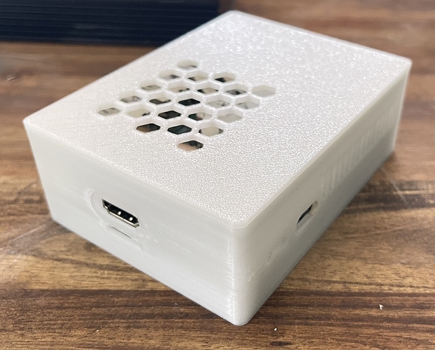
Is the normal ROCK 5B (NO PLUS) Case compatible with the ROCK 5B+?
It is not listed under “ROCK 5B+ Works with” on the website, but i can’t find any information online.
The Board Layout is mostly the same, but im not sure about the HDMI Input, Display Port and SOC Location on the Plus.
ROCK 5B+ non plus case compatibility
They are not compatible. The differences identified so far are listed in the open issue regarding adding the Rock5B+ to SBC Model Framework and SBC Case Builder. Everything is complete to generate cases for the Rock5b+ but it is still marked as unverified until a SBC Case Builder Rock5b+ test case has been printed by someone and verified to work. I don’t have a Rock5b+ unfortunately. The person I’m working with is having some printer issues at the moment so the test case not been completed yet. The test case we are working with is saved as rock5b+_shell in SBC Case Builder if anyone with a Rock5b+ and 3D printer would like to assist.
I generated a STL file from the SBC Case Builder in OpenSCAD.
Sent it off to a local 3d print shop (my Prusa is giving me grief), and should be back on Monday.
Will let you know how that goes.
That’s great, thanks. I look forward to the results and willing to make any changes if necessary.
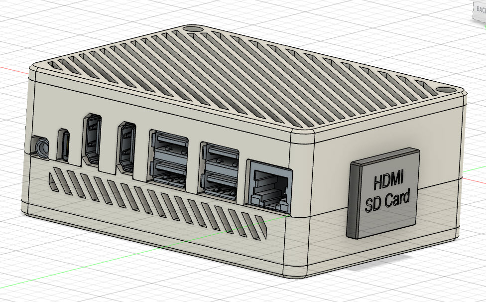
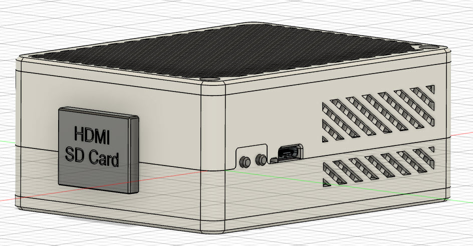
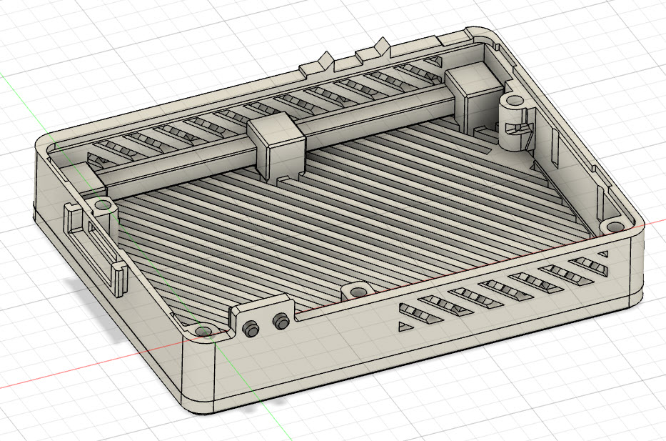
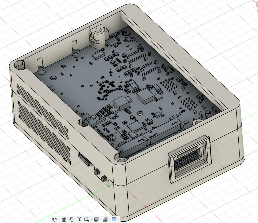
Here’s some CAD images of what I am using. There is quite a lot of detail design, needs an accurate printer. I use a Bambu Carbon X1, and I use ABS as the filament.
One of the design details - i wanted to provide some protection for the TF card - it stick out proud of the case, so I put a cover on it that can be slid off/on.
View from the front - power and reset buttons and usb-c
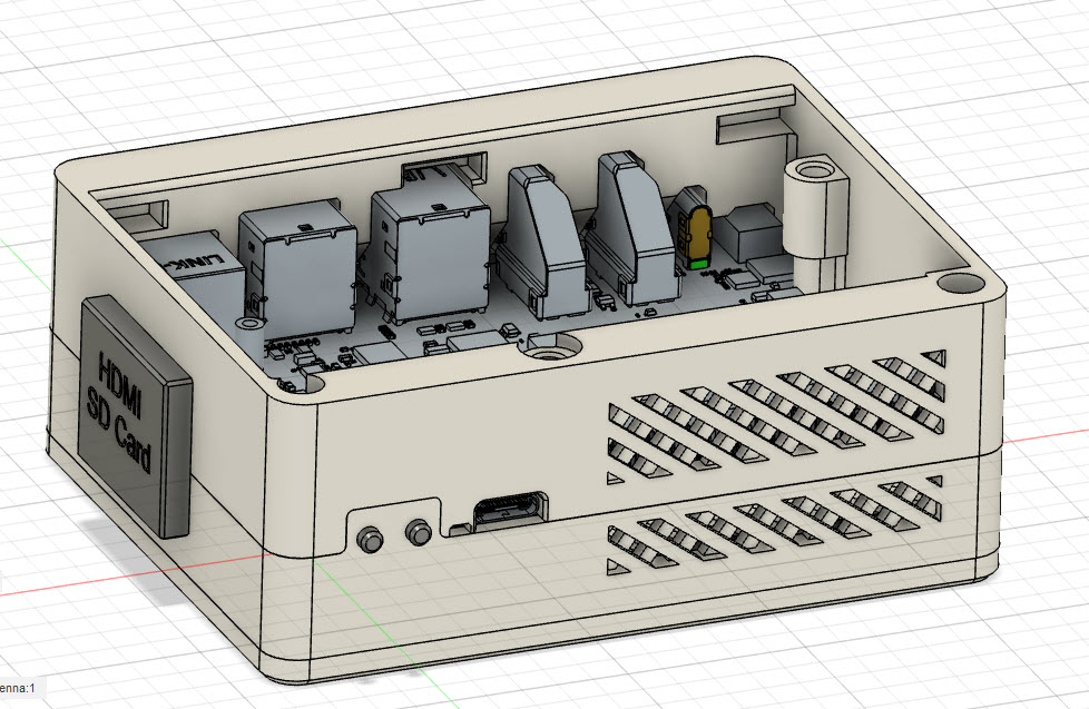
Top cover removed, showing slots for top cover clips
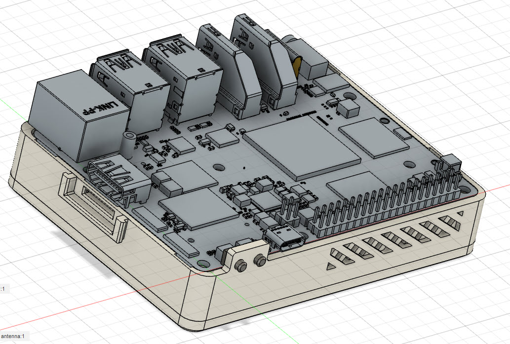
Upper body removed showing board sitting on lower body
PCB removed, showing detail of mid body and base mounting
Underside view to show detail relief needed to allow NVME’s to be installed removed - my earlier design needed some dismantling
The case has 7 parts. The top and bottom covers which clip in to place and are then held in with 2 long m3 screws that also part secure the case assembly. There are the two buttons for power and reset. There is the TF/HDMI cover which slides on/off. There are the two main case halves which secure the pcb and are then further secured with the through screws from the top and bottom case. There are a total of 5 heat assembled m3 thread inserts - 3 for the two case halves and 2 for one of the lids. On my pcb the pcb through holes ar dia 3mm, so needed a little bit of fetling to allow m3 screws go through.
I’ve designed the case so that the nvme’s can be added/removed and the 4G modem can be fitted (that was tricky - the pcb mounting holes are pretty inconveniently positioned. I’ve also made space for the wifi antenna to be attached to the inside of the case. And finally, the cpu fan fits without any problem.
Just printed out a shell case from SBC Case Builder. A couple of minor changes I would suggest:
- Front-side USB-C connector hole could move down by 0.5 mm.
- Bottom standoff near the front SSD connector is too wide and would need to be shaved off to allow a full 2280 SSD to be connected. If the hex layout was rotated so the flat side was pointing towards the SSD instead of the vertex, that would help. A narrower diameter standoff would also help, and/or make it square with the SSD.
- Default standoff/screw arrangement is a bit whack… It’d be better if it defaulted to a nut recess on the bottom or a threaded m2.5 hole on the inside or something.
Nothing that can’t be tweaked in OpenSCAD though. Gonna try re-printing it using the snap case design and the above adjustments, and see how that goes.
Apart from that, amazing tool! Kinda annoyed OpenSCAD doesn’t work on MacOS any more, but hey, I’ve got a Rock 5B+ I can run it on… 
That looks great! Was wondering about changing the NVMe drives too, on the design I used.
Is your design available anywhere?
Oh, also just noticed, next to the 2 reset buttons and to the left of the USB-C socket on the front is the system LED. Maybe a hole should be there? I dunno, it’s kinda in a weird spot where it’s almost at the junction between the top and bottom. Ideas?
It definitely looks odd, coz it’s back-lighting the plastic, but the 2 buttons look like they “should be” LEDS, but they’re buttons.
Design… how does that work?
Thanks for the test print and feedback. I pushed a commit to lower the mask opening for the USBC and increased the case Gap for the rock5b+_shell test case. SBC Case Builder and the sub-module SBC _Model_Framework will need to be updated to see the change.
The Gap was increased because I can see the case top being pushed out by the double stacked USB3 ports and rj45 connector. Regarding standoff and hole size, this case is setup to use 3mm or 2.5mm inserts in the bottom. I used to do just a hole as you suggested but many thought that inserts are ubiquitous enough these days, so the default was changed to use inserts. It’s easy to change in the Standoff Tabs if you need something different and a note in the readme under Notes, Tips and Things to Check was made at the time to alert users.
NVME access is usually created using the Access Panel Tab in SBCCB were one can be created or resized. The reason one is not in the test case is that the position of the NVME drives and the close proximity of the mount screw and connector to the sides of the case prevent the NVME drive from being removed without removing the bottom of the case anyway. This usually can be remedied by over-sizing the case in one or more axis.
This is a common issue when NVME drives approach the physical dimension of the PCB, as in this SBC. An example of over sizing the case to fit a NVME Access Panel in this scenario can be seen in the test case m1s-nvme_shell. To address the Standoff interfering with a mounted NVME, decreasing the size of the top standoffs to 2.5mm should solve the problem. As you said, all of these issues can be solved and are typical things to adjust when a new SBC and cases are added to SBCCB. It’s why test prints are important.
If your going to try the Snap case, definitely read the section called Component Overhang and Case Gap if you haven’t already. The Gap may need to be increased little more to be able to install the SBC in the bottom.
yup, there are some major challenges with access due to the tightly packed layout of the board. There is a similar challenge with the 4G card. I spent a ton of time on minor tweaks to enable removal without case dismantling.But the reality is users are not likely to be swapping cards out very often, so the time taken on design for serviceability is debatable. The Nvme’s have several challenges. One is the mount post’s proximity to the board edge. And then the middle Nvme is very close to the middle board mounting screw. You will see that i have a relief in the mounting boss for the Nvme to be wiggled in to place. I also didn’t want to be pocking anything in for power and reset, so spend the time on buttons that work - the springs in the switches work just fine with small buttons.Another challenge is the wifi antenna. If you need to split the cases to get at the Nvme’s it makes the use of wifi antennae problematic. I wanted to use adhesive foil types and stick and forget. I used a pair with 6" leads which work perfectly.As for availability of my design, I’m happy to post on this forum if folks want it - no probs with stl and step files.
I managed to tweak the standoff arrangement so it works without a problem now.
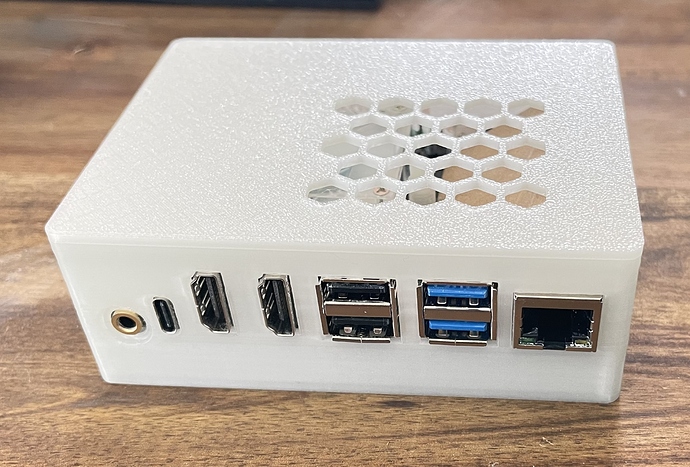
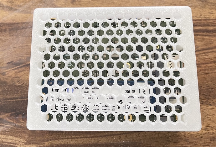
And here are some photos of the final snap-case design (in glow-in-the-dark filament, too!):
I love it!
can you help me creating it. Thanks so much!
