Could someone measure the height difference from the base of the M.2 B-key connector to the top of the Ethernet connectors?
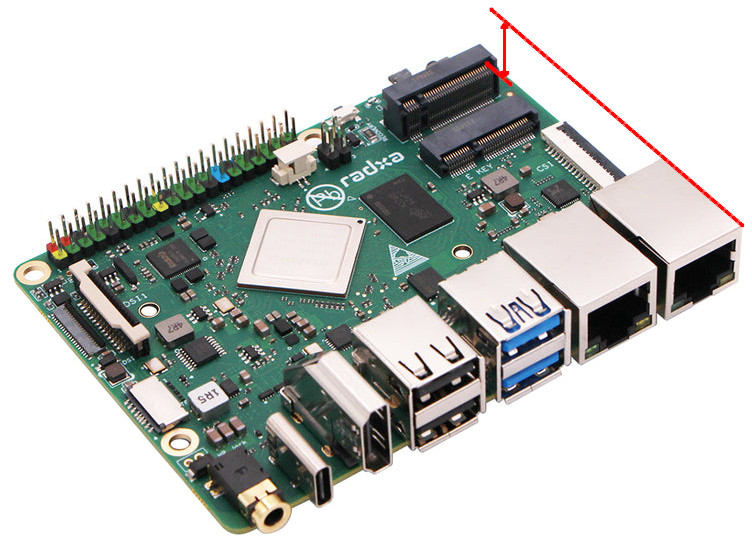
Easiest would be to use calipers from the bottom of the PCB to the base of the M.2 B-key and to the top of the Ethernet connector.
You see, I use miniPCIe-based 4G/LTE modems (Huawei ME909s-120, Mikrotik R11e-LTE and similar), and have for about a decade now (with Linux-based SBCs and OpenWRT-based routers). I am considering getting a Rock 3B and milling my own cast aluminium enclosure for it (where all connectors are inside the enclosure, and only cables come out, for reasons), using Hammond cast aluminium enclosures as a basis, and just milling my own lids with heatsink protrusions into the enclosure.
I can easily design the M.2 B-key to miniPCIe riser board –– it is purely passive, exposing only the USB 2.0 and SIM pins between the two ––, but I believe the Ethernet connectors might be in the way, even though the miniPCIe connector adds a bit of height also. (It is very simple four-layer board, with signal layer between two ground layers, 90Ω differential and 30Ω common-mode impedance on the USB DP and DM tracks, and guard tracks around the UIM/SIM CLK and DATA lines.) I can do a T-shape, though, so the modem sticks outwards from the side of the Rock 3B. Or just use shielded cables, I guess.
Even more help would be to have the actual heights of the component tops (and connector base heights, i.e. base ledge height from the PCB for the M.2 connectors) on the top side, plus side images of the PCB.