I’m trying to get a Rock Pi 4B v1.4 working with two peripherals:
The HifiBerry DAC+ Pro XLR, an I2S based DAC and
a Waveshare 3.5 inch RPi LCD (B) display, which is SPI based
I have adapted drivers for the DAC+ Pro and created the relevant device tree bindings and it works fine. I’ve also created device tree bindings for the display, together with a short wiring harness that connects it either to SPI2, which is free, or to SPI1 which is used for the on-board flash, so that I needed to use an additional GPIO CS line in the device tree binding.
My problem is this: with the DAC+ Pro board connected and the display connected on top of it, if I blacklist the DAC’s kernel modules, the display seems to work more or less fine at a 10MHz SPI clock. I can use modetest to make it display a test pattern.
Probing the SPI1 lines with an oscilloscope shows the clock line being like a sawtooth (or rather what you would get from a square waveform, if the low-to-high transitions were linear ramps), rising to only 2V before dropping back to 0V. I would ascribe this to capacitive loading of the line due to the DAC+ headers and wiring harness, but the curious thing is that the data lines show up much better on the oscilloscope, reaching 3V with minimal capacitive loading showing.
If I allow the DAC+ drivers to load, then the SPI bus becomes unusable at anything above 100kHz or so. The display doesn’t work any more and probing the clock line shows again a sawtooth waveform, now barely reaching 0.5V or so. The data lines are also sawtooth like, although they can reach higher voltages, depending on the number of consecutive high states. In order to get the SPI bus to work, I have to drop the clock speed to something on the order of 100 kHz or so.
The situation is similar with the SPI2 bus.
I’m running Libreelec with a 6.6 version kernel. Any hints as to how this behavior might be explained and what I might look into, would be most welcome.
Thanks for the quick response! I’m using Libreelec currently (because I use the Rock Pi as a media player), so I can’t try out the overlay directly. I would try to install your image, but then I won’t be able to use the DAC+ Pro and without it, I know the display will work fine. It looks similar to mine with a couple of differences:
It seems to be made for the fbtft driver, while I use the tinydrm driver. That shouldn’t affect SPI performance, as far as I can see. I have tried probing the SPI1 lines with just the on-board SPI flash attached, and the clock line is again much more sawtooth-like than the data lines.
There’s an interesting reference to a “high_speed” pinctrl state, but no such state seems to be defined (I can see no pinctrl-1). I see no separate “high speed” SPI pin configuration for the Pi 4B in the Linux kernel. If there’s anything I’m missing, please let me know.
What I wonder though, is why the situation gets so much worse when I load the DAC driver. Note that:
The DAC uses the IS1 and I2C7 interface. I can leave the DAC and display physically connected, leave the device tree bindings for everything enabled and simply not load the DAC’s driver and the SPI bus works ok. If I load the driver, the rise time gets several (maybe 4-5) times larger.
The DAC has no common pins (apart from ground and power pins) on the GPIO header with SPI devices. As I said, it uses the I2C7 and I2S1 interfaces only, which are on different pins.
Thanks for the suggestion! I had tried that and it didn’t make any difference. I now note though that the change doesn’t seem to take effect. I have verified, by loading the running device tree from /sys/firmware/devicetree/base, that the pins are configured as pcfg_pull_up_20ma, yet in /sys/kernel/debug/pinctrl/pinctrl-rockchip-pinctrl/pinconf-pins, I see:
Any idea why that might be? Drive strength does seem to be an issue, although probably not the only issue. If I probe the SPI clock line, configured to run at 10 MHz) on the bare Rock Pi, i.e. without DAC or display attached, I see that it barely manages to reach 3V in the 50ns of on time. That doesn’t seem right.
If I attach the devices but load no drivers, they contribute some capacitance, so that the clock now only manages to reach 2.5V or so in 50ns. If I load the DAC’s driver, it barely manages to reach 0.5V in 50ns.
So one issue seems to be drive strength, in combination with capacitance. Another is that the DAC driver somehow affects the SPI bus, although I can’t see how. Any ideas would be greatly appreciated.
Thanks! Regarding the drive strength, I merely changed pcfg_pull_up to pcfg_pull_up_20ma, as you suggested. I could verify in the running device tree (via the resulting phandle in the pin configuration) that the pin was indeed set in the device tree as 20ma. The kernel debug information showed it as 6ma though.
For the rest I’ve made changes to the dts file for the 4B in the kernel (i.e. I didn’t use an overlay). I include the relevant file below. All other included dts files are as found in the mainline Linux kernel, v6.6.
I had a look at the datasheet for the RK3399 and the GPIO pins for the SPI1 and SPI2 interfaces only go up to a drive strength of 12mA, so that’s why the 20mA setting didn’t take effect. After setting the pins at 12mA, the situation improves in the expected way: When driving the display without the DAC’s driver loaded, the clock now reaches 3V instead of the 2-2.5V it reached before. With the driver loaded it reaches 1V instead of 0.5V.
So the increased drive strength helps, but enabling the DAC’s driver seems to somehow affect the SPI bus, as if the capacitance on the lines is increased. I can’t imagine how though, since the DAC does not use the pins for either of the SPI1/2 buses.
I had noticed another curiosity, which seems like it might be important. When probing the SPI lines I noticed their level pulsating in sync with the blue led on the Pi4B, which is configured as a heartbeat by default.
I can disable the led by setting its trigger to none and the level stays high (well as high as it gets). I can leave it on by setting it to default-on and the level stays low. When probing data lines with lots of consecutive 1s, the level does reach 3V eventually but it takes longer.
So it seems like the SPI GPIO driver can’t provide enough currrent. I now suspect that the deterioriation in the SPI bus’s performance when the DAC is operating, may simply be due to it drawing current, much like the LED.
Another curious thing, is that the status LED, SPI busses and I2S bus are all on different GPIO banks. The 3V3 and 5V lines on the GPIO are all very close to their nominal value. Note that the above happens even when the display and DAC are not connected, probing the SPI NOR flash. It also happens both on the Libreelec and Radxa Bullseye images and both with a 15W power supply and a power bank and two different USB-C cables.
Do you also get such behavior, or is it something on my setup?
I just tried to power it with a 65W laptop power supply. Same behavior: when the blue led is on, the SPI lines seem to be able to deliver only about the half the current compared to when it is off.
Can you try using a dupont cable to connect only the dac’s data cable, 3.3v or 5v data cable through an external supply? to rule out power supply issues
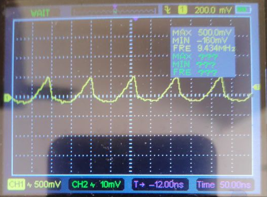
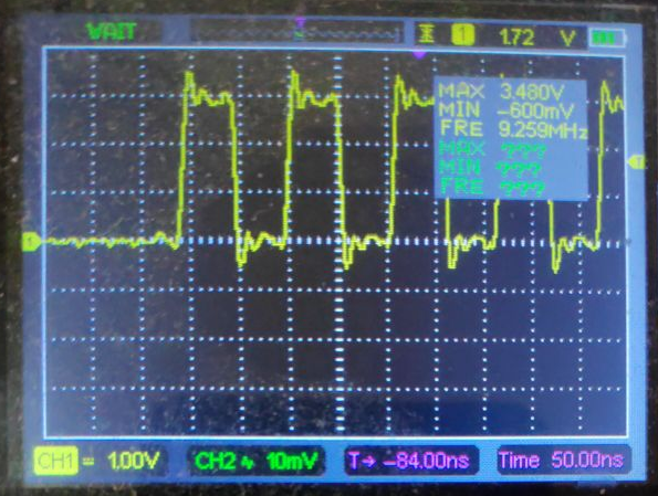
I don’t think it’s a matter of the supply pins. When I have the blue on-board LED off and the display connected, drawing a substantial current to power the backlight, and I read the SPI flash in a loop, this is the waveform I get on the clock line. Note that it reaches 0.5V within the 50ns on time, corresponding to the default 10Mhz setting of the SPI flash in the mainline kernel.
If I turn the backlight off, I get no change whatsoever; it still reaches about 0.5V.
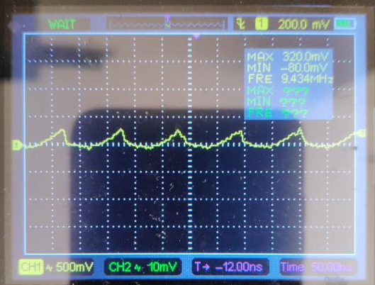
If, on the other hand, I turn on the blue status LED, which gets powered from a GPIO pin, then the waveform is similar, but now reaches only 300mv or so:
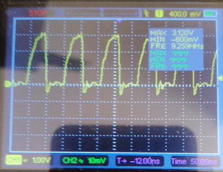
For reference, here are the waveforms with display and DAC disconnected, i.e. with only the Pi 4B. With the blue status LED off, the waveform starts to resemeble a square wave, at least in that it reaches 3V, a bit before dropping back to zero:
I find it puzzling that the SPI signals are pretty close to unusable at the 10MHz default setting for the SPI flash. Perhaps something is wrong with my board (which is version 1.4), although I would find that unlikely. If you could verify whether you get the same behavior, that would be very helpful.
I suppose this happens when the device tries to boot from the on-board SPI flash. So I tried networking the Pi 4B through an ethernet cable instead of WiFi and blacklisting the brcmfmac and hci_uart modules. With the DAC and display connected normally and the blue status LED turned off, the waveform was then fine and the display operated beautyfully, even with the DAC’s driver loaded. Playing audio from the DAC, or turning the LED on, deteriorated the waveform as before.
Again, it seems to me that using any other device that uses the IO pins of the RK3399, perhaps depending on the power domain of the device, deteriorates the SPI’s performance, so that in practice, it’s unusable. Perhaps it’s not just the SPI interface, perhaps other devices are likewise affected. It also has nothing to do with the electrical effects of adding the DAC board and the display and associated wiring. Keeping them on without loading any drivers allows the SPI interface to work fine.
If you have any ideas as to what might be causing this and how to fix it, let me know.
Pins 29, 31, 33, and 37 light up, but every 1.3 seconds or so, the brightness dips twice in short succession, in a rhythmic fashion. Apparently, these pins are 3V by default, and the working pin is 3.3V by default, so I’m thinking that the 3V regulator on this board is unstable for some reason, or that something is pulling the entire bus low, I’d like to set all the pins to use 3.3V, but I can’t find any documentation about how to do that.
I have also separately configured another pin as PWM, set it at a 100ns period and 50% duty cycle to match the waveform of the SPI clock and it exhibits similar behavior. This seems to indicate that the regulator for the 3.0V power domain(s) can’t keep up with the current demanded of it, even with only the on board devices (WiFi, SD card, etc.) connected.
Can you please confirm whether that’s the case and whether the issue is the HW design of the regulator itself, or some sort of configuration issue? If it is a HW design issue, that’d be good to know, so as not to spend any more time looking into this.
Hi! I was experiencing a very similar issue. I have the same rock-pi-4b v1.4 board. As soon as I initialized the sound module snd_soc_es8316:
My SPI (custom LED controller) would stop working
My serial would get noisy (dropped / random characters)
I did not have any issue in kernel 5.10.x, but those started when trying to upgrade to 6.1.x.
I made many changes to the DTS, trying to mimic the configuration from kernel 5.10. The one that did it for me was in arch/arm64/boot/dts/rockchip/rk3399-rock-pi-4.dtsi:
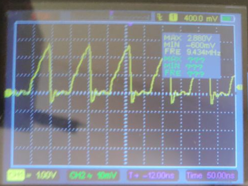
Well, I’ll be… That does seem to fix the problem! The display now works and the clock waveform is excellect (seemingly better than the “good” one I posted last above).
Now I only have to find out why this changes fixes the problem and whether it perhaps breaks something else. At any rate, I can’t thank you enough.
I’ve contacted Radxa about this and they’ve created a PR to revert the change mentioned by Adam above and also push the reversion to the mainline Linux kernel. The change was initially made, according to the commit message by its author because:
As stated in the schematics [1] and [2] P5 the APIO5 domain is supplied
by RK808-D Buck4, which in our case vcc1v8_codec - i.e. a 1.8 V regulator.
Currently only white noise comes from the ES8316’s output, which - for
whatever reason - came up only after the the correct switch from i2s0_8ch_bus
to i2s0_2ch_bus for i2s0’s pinctrl was done.
Nevertheless, as far as I can tell there seems to be an error in the referenced Rock Pi 4 schematics. APIO5 is indeed listed as connected to RK808-D Buck4 on sheet 5, although this is not reflected in the diagram on sheet 3. Furthermore, on sheet 14, APIO5_VDD* is shown as connected to VCC_1V5, VCC_3V0, same as APIO2 and APIO4.
So the above change seems to be a regression. As far as I understand it, the 3D/4A GPIO banks are connected to 3V but the GRF_IO_VSEL register is then configured for 1.8V, which I suppose leads to the drive issues I’ve been having.
On the other hand, the author of the above change, mentions it gets the ES8316 codec working, so they’ll investigate that too, before pushing the change to mainline.