
Hello guys, we plan to make cluster from 10 “Rock3 A” boards
and we want to make custom ups battery management system with monitoring rebooting and other functions. The problem is that we do not want to power the boards from usb-c type connectors because the plan is to make something like our own hats for powering , resetting …etc functions.
I have searched the manuals on the radxa wikis but i can’t find something to be sure which pins to use what voltage and amperage can i put on them. Can anybody help me with this task
Power From Pin Header
Please refer here: https://wiki.radxa.com/Rock3/hardware/3a/gpio
Use pins 4 and 6. The amperage: divide the 5v by your estimate of the power required.
Thanks man
Will it be enough to power the board plus some external cards NVME or usb external disk for example?
is there any amp limit on the pins.
According to the specifications for the DC-DC chip: 5A Available Load Current.
1 Like
Hi,
I have a Rock 3A V1.31
and on usb C I only have 5V and I cannot modify the board that supplies me with power. The union of the two cards makes everything work for me, but I saw that at 5.2V max output I am at the limit, and once it restarted when I inserted a usb wifi key.
Therefore I would like to power 12V which I have available on another header of the power board, before the 5V buck converter.
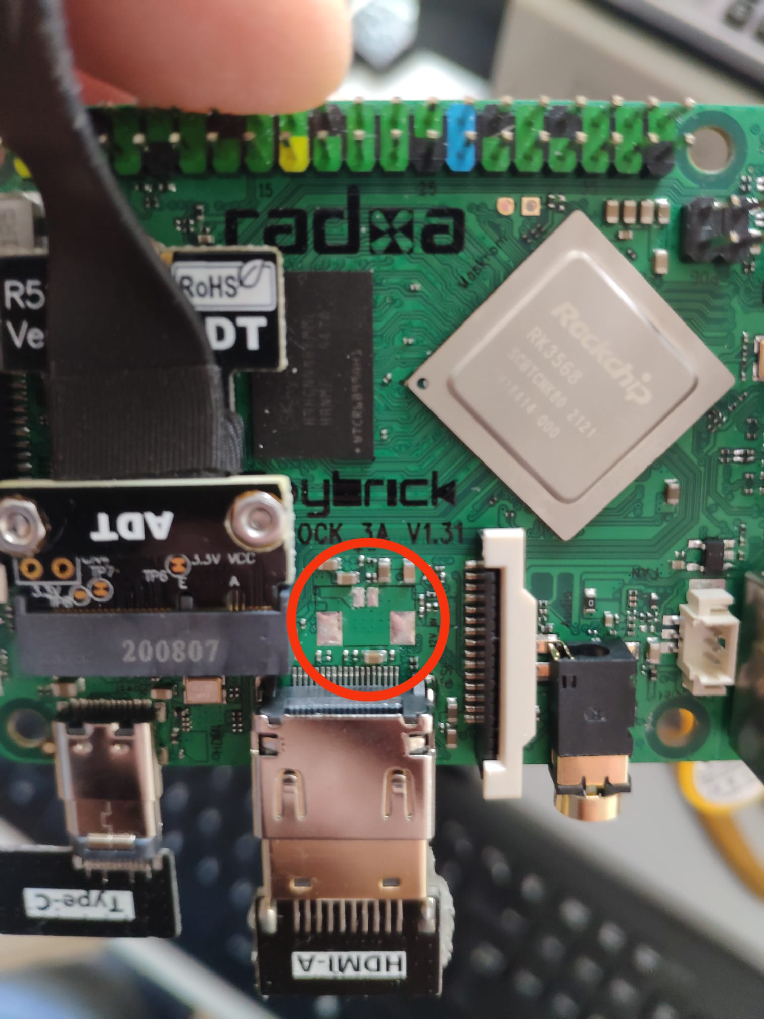
What I ask you, is looking at this picture, I have the latest version of Rock 3A, and there are these circled pads on which I am the input voltage from USB-C, according to you I could solder a connector here, and give power on these pitches?
Version 1.2 had this entry, but this new one I do not find information anywhere.
Thanks for any help!
I already asked a similar question and there was no answer besides supplying 5V on the mentioned GPIO pins.
For hardware v1.2 there’s an external powerr a bit more to the left from where you put the circle (https://wiki.radxa.com/mw/images/2/2e/Rock-3-a-with-label.jpg)
I have hardware v1.3 and this connector is also not preset.
There is also no documentation regarding the PoE header on the board. Looking on pics for the PoE 23W hat, seems it carries voltages, but I don’t have a hat here with me to try out.
On schematics, there’s a VCC12IN which actually comes up on timing before the VCC5IN. I would find totally awesome if I could supply the board with 12V somewhere because I plan to run a cluster along taco boards (which takes 12V and consumes more amps)
@setq can you help us if it is possible?
Many thanks
Yes, I had seen that on 1.2 they had reported this additional power supply, but I don’t understand why they didn’t do it on this new 1.31 as well.
However, testing these two points I find them exactly on the usb-c power cable, so we can define that it is the same thing to power from here, because it always comes to the power supply via PD, this does not happen on 5V GPIOs.
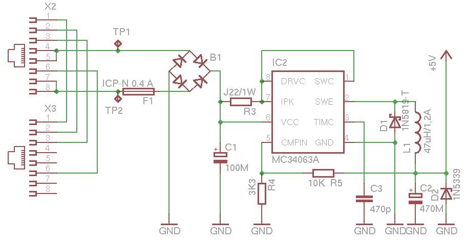
As for the POE, I also need it with a 24V power supply, I found the matches according to the IEEE 802.3af standard 568-A and also 568-B on the 4 pins.
I use a passive PoE system with standard B on two pairs, the power is enough for me, but you need more than 25W, you have to use all the pairs. The two pins I used will go to a 24-12 buck converter and then you have pins on the Rock 3A board, onto which I soldered a connector.
I don’t know if it can help you.
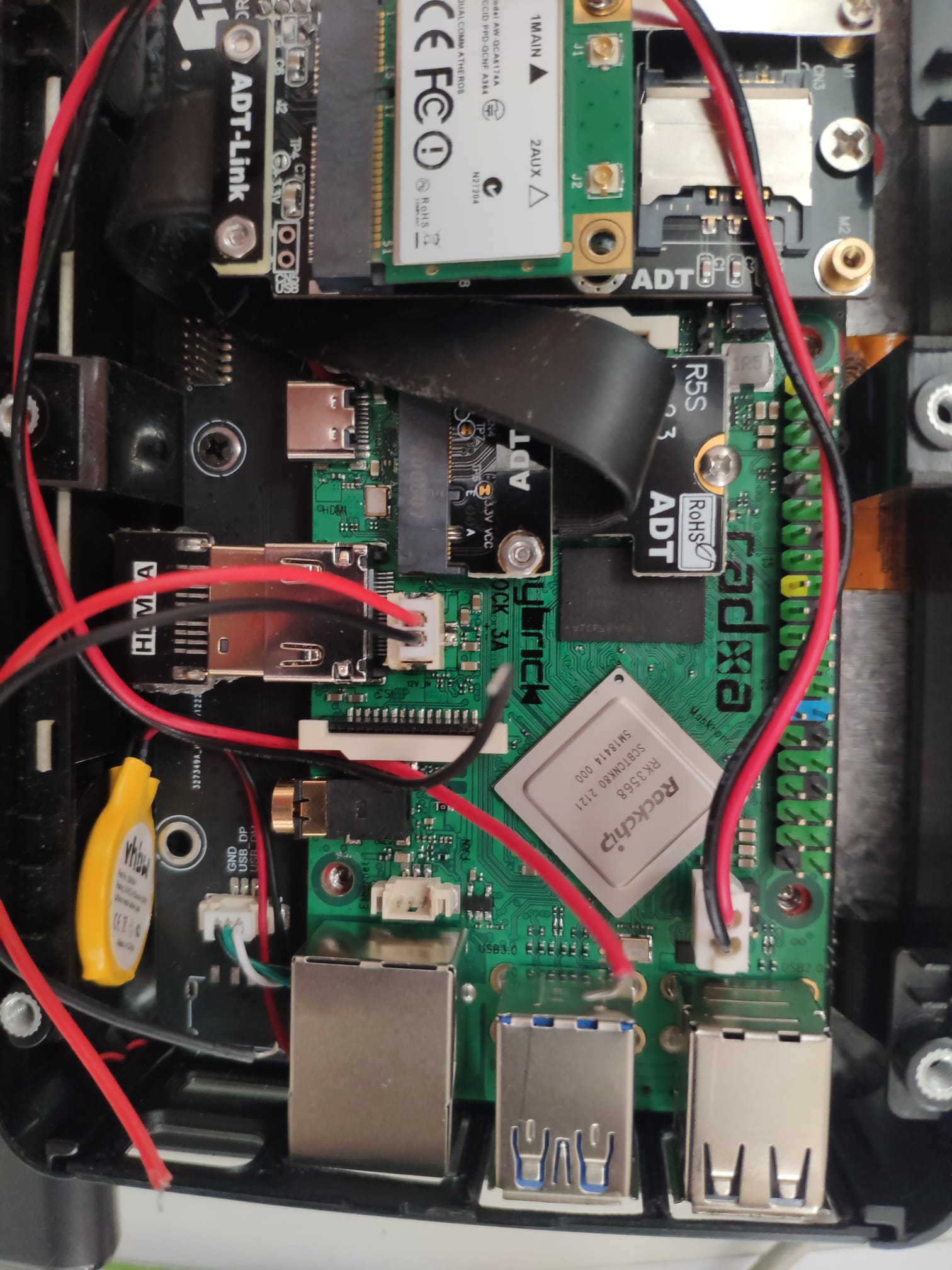
I do not have space to put the PoE hat, this monitor is compact and also has the usb-c power supply designed for raspberry therefore 5V, which also works for me on Rockpi but I had to remove it due to the Pcie modification, with some cards yes restart as soon as it loads the drivers. Better to power 12V, that’s why I soldered the connector near the HDMI I do not have space to put the PoE hat, this monitor is compact and also has the usb-c power supply designed for raspberry therefore 5V, which also works for me on Rockpi but I had to remove it due to the Pcie modification, with some cards yes restart as soon as it loads the drivers. Better to power 12V, that’s why I soldered the connector near the HDMI that goes towards the converter.
Many thanks for the detailed explanation. I will definitely use it as a reference in the future.
So the 4-pin header labeled PoE between the USB and the GPIO headers, is only 5V too?
No, the PoE header refers to the pins of the ethernet connector, which from 8 become 4 by means of the inductors placed in the eth-poe connector. So the voltage you will supply on the network cable, you will find it on the PoE connector near you have GPIO. If your power supply provides 5V you will find 5V, if 24V you will find 24V. So don’t connect PoE directly to Rockpi power supply if you don’t know the source, please measure it first.
The DC in connector supports 6V to 20V input directly on 3A, we did not paste this connector by default because if the user connects USB C and DC in at the same time, it may damage the USB C power adapter.
If you have only 5V, you can just input from the GPIO pin, bypass the DC-DC converter.
1 Like
Sorry, I think I explained wrong what I am trying to achieve (I can understand a bit of Italian).
I don’t want to use a PoE power supply. I want to have my own DC power supply (12V or 19V, for example) and connect to the RockPi 3A. This is because I have 7 boards here and would like to use a single PSU. So I was asking if 12V or 19V could be connected into the 4 pins labeled “PoE” on the RockPi 3A, between the GPIO and the USB connectors.
(Let me try to write myself in italian, to avoid misunderstandings  )
)
Non voglio usare un alimentatore PoE. Voglio avere il mio alimentatore CC (12V o 19V, per esempio) e collegarmi al RockPi 3A. Questo perché ho 7 dispositivi RockPi 3A qui e vorrei utilizzare un unico alimentatore. Quindi stavo chiedendo se 12V o 19V potessero essere collegati ai 4 pin etichettati “PoE” sul RockPi 3A, tra il GPIO e i connettori USB.
(the 12V PSU is 200W)
Does the same applies to the pins from the PoE header (4 pins between the USB and the GPIO pins)?
I ask this because I would like to feed the 3A with a 12V power supply, so it could be shared between other boards (taco) without having an additional step-down to 5V.
Also would be nice if I could use those pins instead of having to solder an additional connector, even better if the regulator in the board can handle up to 20V input, as 19V power supplies are very easy to source.
Thanks.
Si ok, la scheda supporta fino a 20V, quindi nel tuo caso va benissimo. Io invece uso un alimentatore PoE 802.3af da 24V 1A e non posso rischiare che bruci tutto, quindi dopo i 4 pin PoE metto un convertitore che mi abbassi sotto i 24V, tipo 12V e vado sicuro.
Alimentare PoE significa che al tuo dispositivo arriva un solo cavo di rete dove all’interno viaggiano Dati + Alimentazione, senza aggiungere alimentazione esterna. Se a tu non hai un alimentatore PoE, dimentica quei 4 pin perchè non vanno ad alimentare niente sulla scheda, ma sono tirati fuori dal connettore ethernet.
Semplicemente usa o tutti cavi USB-C collegati al tuo alimentatore da 200W o salda il + e - della tensione del tuo alimentatore su quei punti che ti ho segnalato su.
Ecco il mio PoE
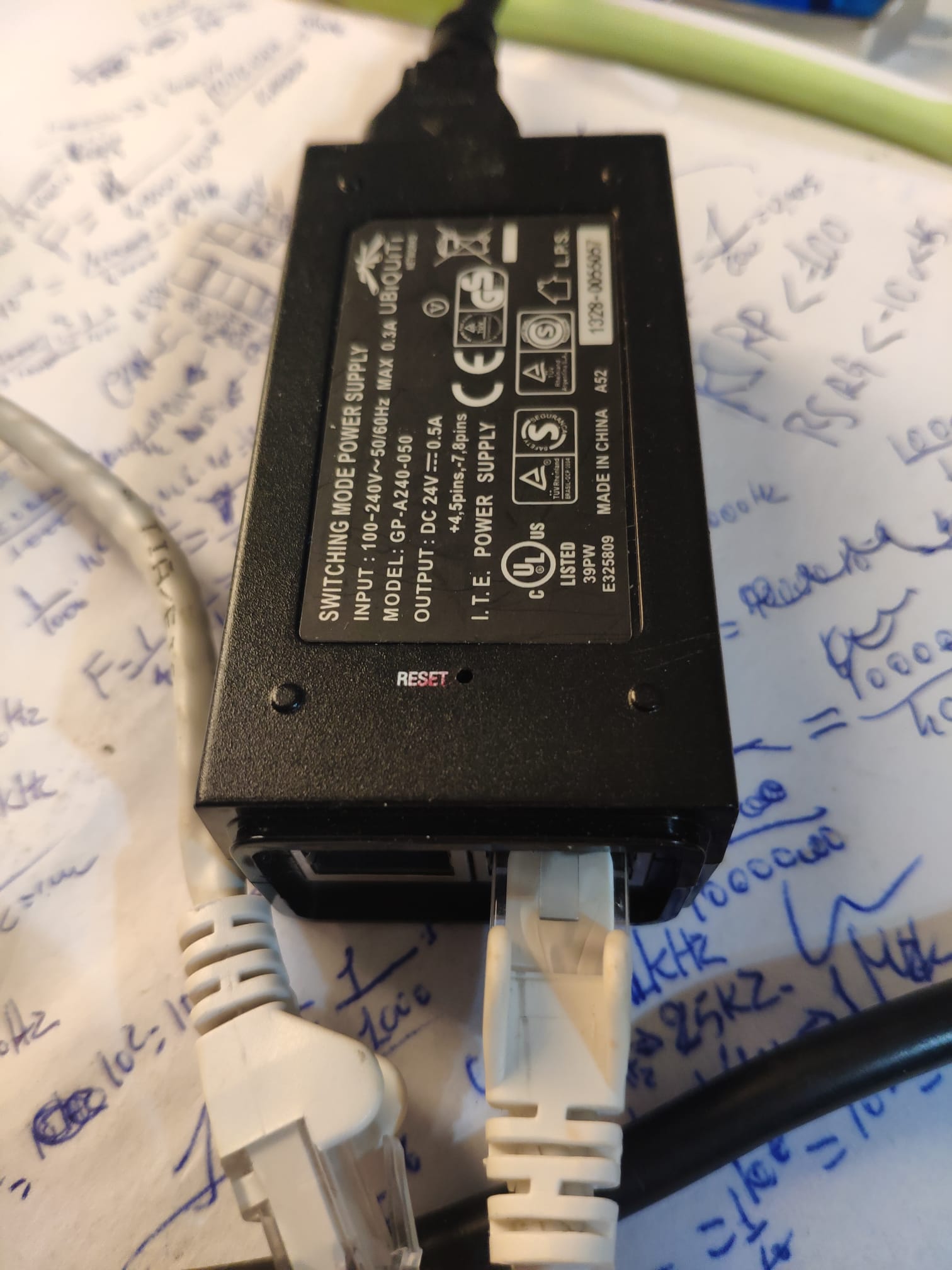
Okay, but in the hardware diagrams you signal that those pads are power.
In my case the LCD already has the usb-c 5V output because it was for raspberry and the Rock 3A also worked, and for this reason I chose this model of Radxa, but when I removed the wifi card and inserted a 4G / pcie card LTE, by itself it would restart the board after loading and I found that at 12V it doesn’t. It didn’t always happen, but since I’m building a 24V IoT industrial equipment I need security and stability, that’s why I go to power with that connector with my buck that supports up to 28V.
I see. Thanks for the explanation. I was under the impression that the 4 pins carried only power by the thickness of the traces. After reading your explanation it makes sense to carry power to the HAT and not from the HAT.
I am not well versed in USB-C specifications. I have thought that the board was designed to handle only the 5V 3A PD profile (PD 3.0). Which leads me to two questions:
- Is it possible/designed to handle 12V and 20V profiles?
- Can I feed it 12V and 20V on the USB-C (in the correct pins) without the handshake from PD? [procedura di regolazione?]
If that is a yes, then I’m happy since having 7 USB-C breakout connectors + cables is better than stepping down the voltages to 5V.
Grazzie mille
yes, the PD makes sure that the board asks for power based on the absorption, communicating with all 4 wires of the USB-C.
But then quietly power it directly at 12 and 20V DC, only I would avoid giving 20V continuous, since it is the maximum supported, you give it max 18 or 19V 2A to board.
Go quietly also with 12V!
Mine has to operate in an industrial environment, and I only have 24V there and it would have been nice if I could give this voltage directly, I would have saved components.
12V is already good enough for me now. Waiting for USB-C breakout boards to arrive.
Many thanks.