8.3.2 Analog Interface
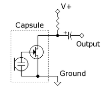
Fig. 8-8 Input DC-blocking capacitor
The capacitance and input resistance from a high pass filter. For example, when the gain of
the MIC module is 20dB, the input resistance is 45kΩ and 0.1uF DC-blocking capacitor is
used, the lower cut-off frequency is:
The capacitance of the DC-blocking capacitor should be determined by the minimum input
impedance and application requirements. If the output of microphone is single-ended, the
audio ADC input should be connected as following figure.
With an electret you will prob be using the single-ended type of circuit and you should use high quality caps that really should as close to the adc inputs as possible and that might be the problem.
Caps should be poly film type caps but also bi-polar audio electrets can be used but guess you could use ceramics at a push.
I have forgot from memory but the examples they show the capacitor value is either too high or too low as you prob want a higher cutoff to try and stop some of the DC hum but from experiment it doesn’t matter.
You can use alsamixer to set the bias voltage or amixer contents and then amixer cset to set values.
Whatever I did with different values of gain bias voltage, capacitor values I always ended up with a really bad SNR where it was too noisy to use.
I have a hunch there is far to much unshielded track that is too long and we can only put capacitors at the end of the run and not right at the input of the ADC so its an impossible situation.
Its a real shame as the RK3308 is this amazing audio SoC and a 8x audio quality ADC is an absolutely unique selling point but likely killed by implementation due to just a few caps and track run to gpio.
Radxa offer PDM but when you employ the overlay it cuts the 2 channel dac output and have not really worked out the I2S yet.
For some reason also they persist with 2.54mm headers and not enough GPIO for pins and the revisions have been playing musical chairs with the pin mux each revision and only x4 ADC pins still remain and they are still pretty pointless due to the noise and DC hum of the various other pin tracks that surround.
Really radxa should of gone for max adc gain prob backed off to about 70% wih fixed capacitors in a single ended config on the pcb as close to the SoC pins as possible but they don’t and they route out all the way to the gpio header with zero filter on that track length to the ADC so effectively the ADC is broken.
Such a shame as personally I think that SoC and function is amazing but currently for what I want to use its unusable.
Even with non electrets and single ended preamps or mems analogues what ever I have tried hits that noise barrier and likely not enough Gnd shielding and far too much track length before the decoupling capacitors.
The resistor on single ended should approx. match impedance of electret so that v out is half way, V+ being your bias.
You can get a real advantage with AEC with close direct non reverberant noise using unidirectional electrets and also spare ADC channels for loopbacks so you can sync audio in/out for further AEC routines but the current layout is sort of broken and such a shame as this is an amazing little audio SoC.
@jack think that is the prob and to much trace before what is essential dc blocking filters and also the differential input that way is also doubling picked up noise, as is only pulled to gnd @ gpio.