Hey. Just wondering. Am I not thorough enough or is there no exact pinout diagram for the NX5?
I wanted to make a custom board for it, but can’t see anything in the docs.
NX5 SODIMM connector pinout
Hi. I am returning to this topic since I finally have the time to sit down and design.
I wanted to ask a follow-up question.
Does any PCB design program have the schematic for NX5 or CM5?
I mean both the electrical diagram and the diagram for routing traces on a carrier board.
I wanted to use EasyEDA (I’m not a professional), but it’s not there.
The schematics are in the above link. You’ll need to be more specific. What do you mean “routing the traces on a carrier board?”  You should reference the SODIMM connector on page three of the NX5 module schematic.
No. They aren’t. I don’t understand what you don’t understand. Maybe there’s a language barrier here because I’m not very familiar with electronics nomenclature in english (I mostly do programming)
A schematic in a .pdf doesn’t mean anything when you want to use PCB design software.
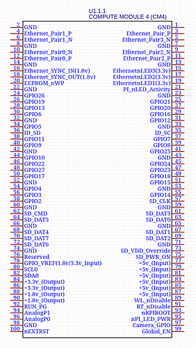
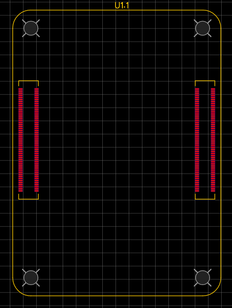
I’ll use RPi CM4 as an example and talk like we’re both stupid here.
- I need this thing for making the schematic.
- And this thing for designing the PCB itself.
Yeah, that’s not called a schematic, it’s called a schematic symbol and footprint. I have one for Eagle if you want. I can upload it here later today. But only for the CM5.
The Radxa CM5 and NX5 IO board schematics can be found:
We offer OrCAD for schematic and PADs for PCB Layout. An export of Altium Designer project is also available.
Yeah, we sometimes colloquially call that “element schematic” and that’s the name I was used to.
Thanks, I’d appreciate those Eagle files.
But that’s not exactly what I’m looking for. You only offer either the files for the module PCB itself or the whole IO board, while I would like to design my own IO/carrier board. And for that I need the modules’ mechanical dimensions and SODIMM/BTB electrical connections inside the design software. I hope you understand what I’m saying. Sorry for not being very clear.

