Dear forum
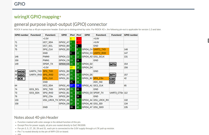
I’ve been trying to get the waveshare can shield https://www.waveshare.com/2-ch-can-hat.htm to work on the RockPi4SE, using Debian on kernel 5.10.X. The shield is based on two MCP2515 IC’s, both connected to the SPI1 bus on the RockPI4SE. The shields pin mapping can be found in the image below.
After spending a lot of time, trying various dts file edits:
- The can0 successfully initializes at startup
- It’s possible to set the bitrate of the canbus
- It’s possible to set the txqueuelen of the canbus
- Edit: I can send can messages, as long as the INT0 remains high
This results in the following “journalctl” output after reboot:
PS: My current dts file can be found at the bottom of this post.
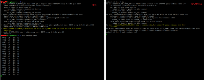
Everything appears great and functional, until I do “candump can0” without seeing any data on an active bus. I’ve an RPI4 connected to that same bus, which correctly dumps received messages to the console. The difference between the RPI and RockPI can be seen in the image below:
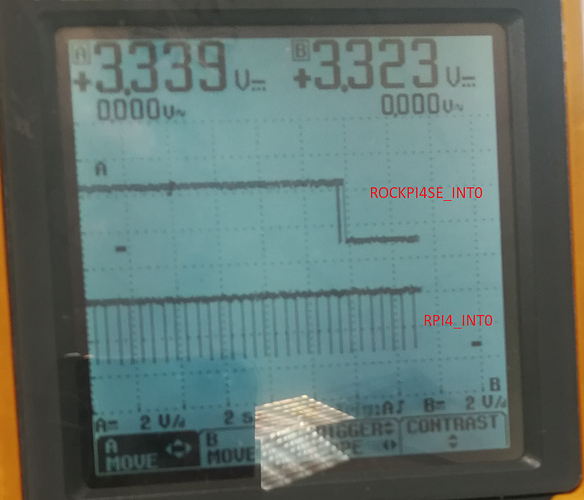
After doing some further hardware tests, I noticed that the RockPi doesn’t respond to the INT0 pin being pulled low. INT0 remains high until I set the bitrate, after which it drops low and remains low. As can be seen in the image below.
Anyone any idea how to get the interrupt pin to work? Am I doing something else wrong?
Thanks in advance!
Best regards
Tim
The dts file I’m using:
/dts-v1/;
/plugin/;
/ {
compatible = “rockchip,rockpi”,“rockchip,rk3399”;
/* enable spi-dev for spi1 */
fragment@0 {
    target = <&spi1>;
    __overlay__ {
        status = "okay";
    };
};

/* the interrupt pin of the can-controller */
/* Hat uses physical pin 16 (GPIO4_D2) which converts to gpio 154 */

fragment@1 {
target = <&pinctrl>;
    __overlay__ {
        can0_pins: can0_pins {
            rockchip,pins = <4 154 1 &pcfg_output_low>;
        };
    };
};

/* the clock/oscillator of the can-controller */
fragment@2 {
    target-path = "/";
    __overlay__ {
        /* external oscillator of mcp2515 on SPI1 */

        can0_osc: can0_osc {
            compatible = "fixed-clock";
            #clock-cells = <0>;
            clock-frequency  = <16000000>;
            clock-output-names = "can0_osc";
        };
    };
};

/* the spi config of the can-controller itself binding everything together */

fragment@3 {
    target = <&spi1>;
    __overlay__ {
        #address-cells = <1>;
        #size-cells = <0>;
        can0: mcp2515@0 {
            reg = <0>;
            compatible = "microchip,mcp2515";
            pinctrl-names = "default";
            #pinctrl-0 = <&can0_pins>;
            spi-max-frequency = <10000000>;
            interrupt-parent = <&gpio4>;
            interrupts = <16 8>;
            clocks = <&can0_osc>;
            vdd-supply = <&vcc3v3_sys>;
            xceiver-supply = <&vcc3v3_sys>;
        };
    };
};


__overrides__ {
    oscillator = <&can0_osc>,"clock-frequency:0";
    spimaxfrequency = <&can0>,"spi-max-frequency:0";
    interrupt = <&can0_pins>,"rockchip,pins:0",<&can0>,"interrupts:0";
};
};


