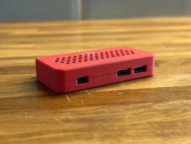
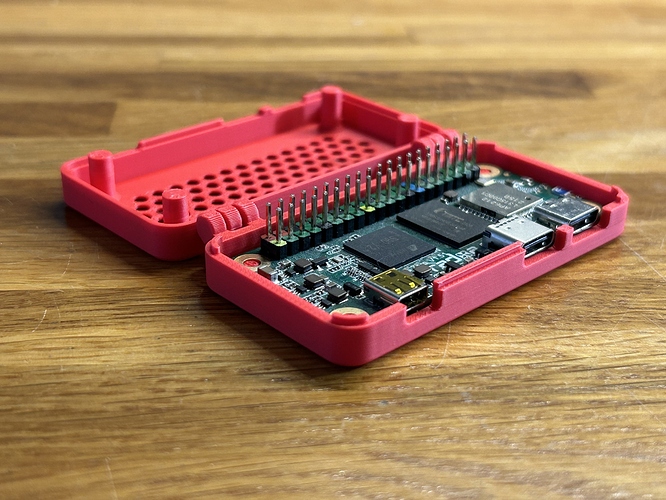
Hello everyone!
I was wondering if there is any case available to house the Raxda Zero; I would like to carry it around with me in my backpack and power it using a powerbank.
Is there any Radxa Zero Case?
You can try pi zero case, it should fit except for the uSD slot.
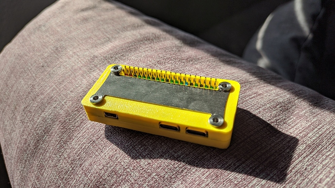
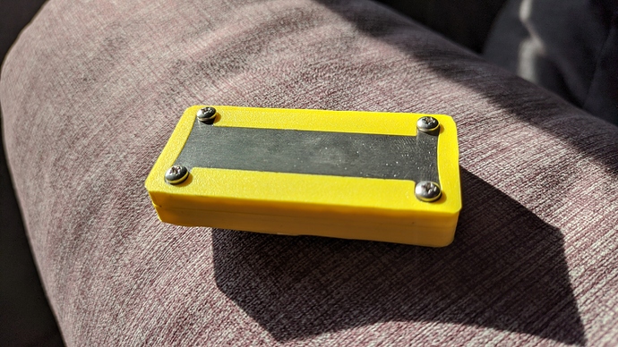
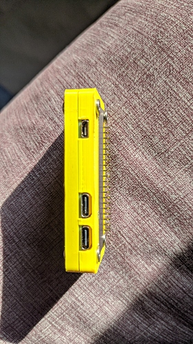
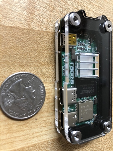
You will not be able to use a Pi Zero case without making modifications: Raspberry Pi Zero has micro-USB connectors not USB-C connectors so the holes are smaller, and the SD card is on the opposite side of the board to the Radxa Zero. I don’t need the SD card slot (as booting from eMMC) so I hacked a Flirc Zero case with a dremel (not pretty, but works):
If you can modify a Pi0 3D print file for the Radxa I will print some and put them on Etsy for slightly over cost plus shipping.  my Prusa printer comes in in early October and I’ll be learning how to use 3d models but I’m not ready to start modifying files yet. Anyone who feels comfortable modifying files send me a message and I’ll print some test cases.
Can you share the STL file? thanks.
This style case fits without too many issues
Can use a plastic washer as a spacer if you need more clearance on the underside, but they don’t block the USB-C ports given it has an open side.
This is the one I’m using
I’ve used a couple cases while tinkering with the Zero.
This one fits reasonably well and has a little pop-out window for the GPIO headers, but the slot for the microSD card is located a little to high to accomodate the protruding microSD on the Radxa Zero (since it’s on the ‘bottom’ of the board and not the ‘top’), so you’ll either have to file it down a little or use the Radxa Zero without an inserted microSD card.
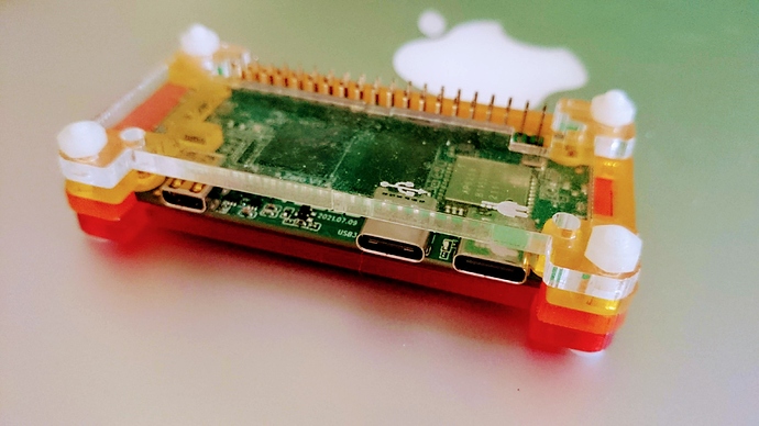
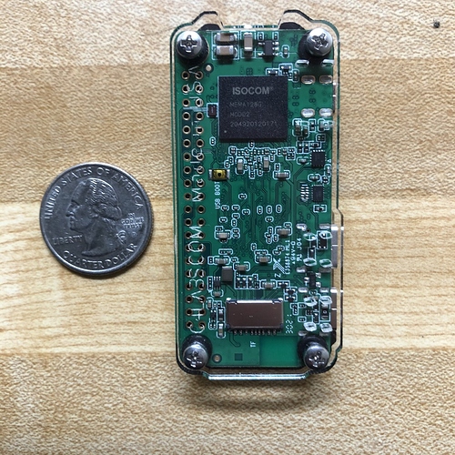
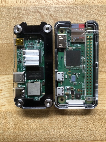
My current favorite though, is this one. I had to use two kits because I needed extra washers to elevate the board away from the bottom acrylic panel to make room for the components on the bottom and I used two of the C-shaped ‘bottom’ interior spacers rather than the regular ‘bottom’ and ‘top’ spacers to allow more room for the USB-C ports. The SD card fits but you have to use tweezers to remove it. 
A couple pics for comparison:
https://www.thingiverse.com/thing:1167846 is a really good case for a Pi Zero, though not sure how well it would work for the Radxa Zero. It’s open, so it may be modified by someone with more skill at 3D modeling than I am.
Seems someone also made this one, though the lack of airflow concerns me with a quad core SoC: https://www.thingiverse.com/thing:4980944
Very awesome! I’ll have to try this out soon! 
I know the flirc case has cooling built into the case. How well does it work with the Radxa Zero? Did you need an extra thermal pad? if you get good perfomance out of it, I may just have to pull the trigger and get one now haha.
The thermal pad that ships with the flirc case was fine and the S905Y2 chip is in a similar position to the Pi’s Broadcom chip and overlaps well with the internal “finger” that draws heat. I normally power the board from a UART cable on GPIO pins so the pins are exposed which also allows heat to escape from the case, and the kind of testing and dev work I do is lightweight so I don’t stress the board. For me the board reports temps in the 35-45ºC range and the case is never more than “mildly warm” to touch. Use-cases with desktop distros and retro-gaming will generate more heat.
NB: Modifying the case to fit the Radxa board needs a dremel or files to widen the USB ports. If you don’t have one, don’t think about getting this case.
Awesome! Thank you so much for the info. I think I am going to go grab one now. Ive done a lot of heavy modification with full sized pcs so this will be no problem at all. I just need a pocket linux machine to test hard drives at customer sites. Its too small of a job to carry around and entire laptop for it.
I’ve tried to put my Radxa Zero into the case, but it seems the hole for the USB Type C near the end of the board (by the “5V” mark on the case) is a little too thin, and needs an extra 1mm or so in the direction of the mark. It also fails to sit flat in the case, possibly related to the holes not being quite large enough.
My suggestion, widen the hole by the “5V” marking towards that marking by 1mm, and increase their height (or move them upwards) by 1mm as well.
Hi everyone!
I’ve tried to use or remix several cases from Thingverse, but I had different troubles with them. So I decided to design my own from scratch in Shapr3D. Maybe you will find it useful too.
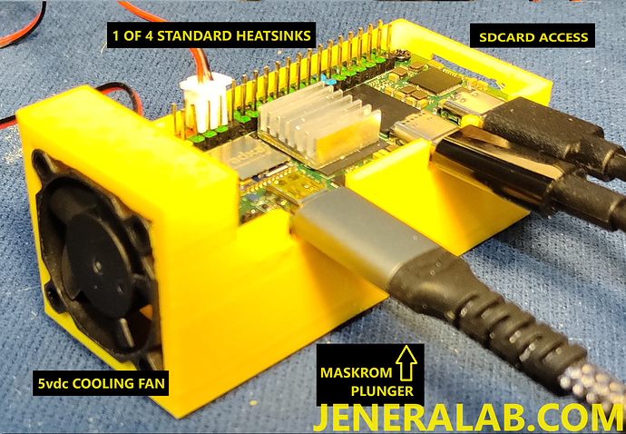
I have a Case for the Radxa Zero3w in design right now for 3D printing. It is still being refined, but includes a plunger for the maskrom switch, a place for 4 heatsinks, a 5Vdc fan, a lid (unrefined), and the plunger. The .stl file should be available on my new website and YouTube channel in a few days. Any inputs would be appreciated. Version 7 is on the 3D printer right now with lid and plunger for the final (hopefully) last test fit. Any suggestions for improvement would be greatly appreciated. There will be more versions available including a latch held USB hub and possibly a latch held mini-breadboard.
Visit *
Still haven’t been able to put the final version of this case on Thingiverse for si=on=me reason. Any suggestions?
Rough temp tests using the following command:
sudo cat /sys/devices/virtual/thermal/thermal_zone0/temp
(there is zone0 and zone1)
using a 30mmx30mmx10mm fan off of the boards pins 4 & 6 on two heat runs:
test 1 fan running zone0 = 42250 = 42.250 C
fan running zone1 = 38333 = 38.333 C
test 2 fan NOT running zone0 = 85000 = 85.000 C
fan NOT running zone1 = 81666 = 81.666 C
test 3 fan running zone0 = 50625 = 50.625 C (after test 2 + 5 minutes)
fan running zone1 = 46666 = 46.666 C
test 4 fan NOT running zone0 = 85000 = 85.000 C (after test 3 + 5 minutes)
fan NOT running zone1 = 81666 = 81.666 C
Thanks to the forum member (I cannot now find the member or the post) for showing the code & conversion to Celsius degrees in his post about running display screens at high FPS and optical recognition.
Improvements to the case as shown include a 30mmx20mmx6mm heatsink under the Zero3W and 3 heatsinks on the 3 hot chips on top plus a “snap-on” lid with access to the GPIO pins.
If there is an inaccuracy in the coding or conversion, please let me know.
Also, if there is a way to get this info or other system inner parameter info within Python3, please let me know.
Just created a case for the Radxa Zero, might work well with the 3w too
https://makerworld.com/en/models/1205239-radxa-zero-w-case-hinged#profileId-1218963

