Is there a way to increase SPI clock speed?

Hi,

I’ve attached a SPI LCD display (ST7789 - 240x240 pixels) on the zero board.
It work fine but it’s limited to less than one frame per seconde probably because the SPI device is limited to :
param_spidev_max_freq=10000000

So what i did:

  • change param_spidev_max_freq in /boot/uEnv.txt
    overlays=meson-g12a-spi-spidev
    param_spidev_spi_bus=1
    param_spidev_max_freq=120000000

  • recompile and install the kernel and especialy meson-g12a-spi-spidev.dts file :

root@debian:/home/papy/radxa-zero-sdk/kernel# cat ./arch/arm64/boot/dts/amlogic/overlay/meson-g12a-spi-spidev.dts
/dts-v1/;
/plugin/;

/ {
	compatible = "radxa,zero", "amlogic,g12a";

	fragment@0 {
		target = <&spicc0>;
		__overlay__ {
			pinctrl-0 = <&spicc0_x_pins &spicc0_ss0_x_pins>;
			pinctrl-names = "default";
			#address-cells = <1>;
			#size-cells = <0>;
			spidev@0 {
				compatible = "spidev";
				status = "disabled";
				reg = <0>;
				spi-max-frequency = <120000000>;
			};
		};
	};

	fragment@1 {
		target = <&spicc1>;
		__overlay__ {
			pinctrl-0 = <&spicc1_pins &spicc1_ss0_pins>;
			pinctrl-names = "default";
			#address-cells = <1>;
			#size-cells = <0>;
			spidev@0 {
				compatible = "spidev";
				status = "disabled";
				reg = <0>;
				spi-max-frequency = <120000000>;
			};
		};
	};
};

But the display is still limited to less than 1 frame per second. I don’t have an oscilloscope to check the SPI clock speed but it always seems limited to a very low speed

Is there a way to increase the SPI clock (maybe I use a bad multipler)?

Thanks in advance
I go further in my search. If I look at https://wiki.radxa.com/Device-tree-overlays :

param_spidev_max_freq (int)
Maximum SPIdev frequency
Optional
Default: 10000000
Range: 3000 - 100000000

So, I can apparently set the clock up to 100 Mhz, but even after a recompile and even if I can see that spi.max_speed_hz is well set to 100 Mhz in spidev (I also check that it’s well set with “dtc -I fs /sys/firmware/devicetree/base”), the SPI is still very low (probably 10 Mhz). I’ve tested on both spi on 2 different Radxa Zero.

Do you have any idea? Is there a hardware clock limit to only 10Mhz ?

I found an interesting error that I miss previously in “dmes” when I activate SPI.
I have the same error log on 2 different Zero SBC.
I’ve tested with 2 debian raw images (one from january and the last one) and I even rebuild the kernel and I’ve always the same problem. To reproduce this kernel error, you juste have to activate spidev in /boot/uEnv.txt

overlays=meson-g12a-spi-spidev
param_spidev_spi_bus=1
param_spidev_max_freq=10000000

I suspect that the limited SPI clock speed is related to this problem

The log is bellow:

[    2.318384] random: fast init done
[    2.425063] meson-vrtc ff8000a8.rtc: registered as rtc0
[    2.425136] meson-vrtc ff8000a8.rtc: setting system clock to 1970-01-01T00:00:02 UTC (2)
[    2.441078] ------------[ cut here ]------------
[    2.441120] /soc/bus@ffd00000/spi@15000/spidev@0: buggy DT: spidev listed directly in DT
[    2.441208] WARNING: CPU: 2 PID: 1384 at drivers/spi/spidev.c:742 spidev_probe+0x144/0x268 [spidev]
[    2.441220] Modules linked in: spidev(+) rtc_meson_vrtc axg_audio(+) sclk_div clk_phase
[    2.441251] CPU: 2 PID: 1384 Comm: systemd-udevd Not tainted 5.10.69-10-amlogic-g617a45dd0fce #amlogic
[    2.441262] Hardware name: Radxa Zero (DT)
[    2.441271] pstate: 60000005 (nZCv daif -PAN -UAO -TCO BTYPE=--)
[    2.441283] pc : spidev_probe+0x144/0x268 [spidev]
[    2.441294] lr : spidev_probe+0x144/0x268 [spidev]
[    2.441301] sp : ffff8000140e3900
[    2.441307] x29: ffff8000140e3900 x28: 0000000000000100
[    2.441317] x27: ffff0000038db000 x26: 0000000000000001
[    2.441328] x25: 0000000000000019 x24: ffff800011771000
[    2.441338] x23: ffff800008e5c058 x22: 0000000000000000
[    2.441348] x21: ffff000000828800 x20: ffff000000828800
[    2.441359] x19: ffff800008e5c038 x18: ffffffffffffffff
[    2.441369] x17: 0000000000000000 x16: 0000000000000000
[    2.441379] x15: ffff80001166e948 x14: 000000000000012a
[    2.441390] x13: ffff8000140e35a0 x12: 00000000ffffffea
[    2.441400] x11: ffff8000116fb270 x10: ffff8000116e3230
[    2.441410] x9 : ffff8000116e3288 x8 : 0000000000017fe8
[    2.441422] x7 : c0000000ffffefff x6 : 0000000000000001
[    2.441432] x5 : 0000000000000000 x4 : 0000000000000000
[    2.441442] x3 : 00000000ffffffff x2 : ffff80001168b200
[    2.441452] x1 : fc3801c1fb1f1a00 x0 : 0000000000000000
[    2.441464] Call trace:
[    2.441474]  spidev_probe+0x144/0x268 [spidev]
[    2.441489]  spi_drv_probe+0x84/0xe8
[    2.441500]  really_probe+0x114/0x500
[    2.441509]  driver_probe_device+0xfc/0x168
[    2.441519]  device_driver_attach+0x74/0x80
[    2.441527]  __driver_attach+0xb8/0x168
[    2.441535]  bus_for_each_dev+0x7c/0xd8
[    2.441544]  driver_attach+0x24/0x30
[    2.441552]  bus_add_driver+0x15c/0x240
[    2.441560]  driver_register+0x64/0x120
[    2.441568]  __spi_register_driver+0x4c/0x58
[    2.441579]  spidev_init+0xa4/0x1000 [spidev]
[    2.441590]  do_one_initcall+0x60/0x1d8
[    2.441601]  do_init_module+0x58/0x1f8
[    2.441613]  load_module+0x21ec/0x26e8
[    2.441621]  __do_sys_finit_module+0xc0/0x128
[    2.441630]  __arm64_sys_finit_module+0x20/0x30
[    2.441641]  el0_svc_common.constprop.4+0x70/0x1d0
[    2.441650]  do_el0_svc+0x24/0x90
[    2.441661]  el0_svc+0x14/0x20
[    2.441669]  el0_sync_handler+0x90/0xb8
[    2.441677]  el0_sync+0x180/0x1c0
[    2.441685] ---[ end trace a2f9de1855f57e5d ]---
[    3.102288] usb 2-1: new SuperSpeed Gen 1 USB device number 2 using xhci-hcd

I got a good fps on my ST7735s lcd, although when i try to run large videos and scaled down to 128x128, i tends to get choked on cpu since it tries to downscale it and write to framebuffer.
But for relatively small resolution video / display, it can be handled ok.

I’ve make a bench raspberry vs Raxda zero on the same SPI display 256x256 :
Raspberry can display 500 frames in 37 seconds (and It could be probably be improved)
Raxda zero can display 500 frames in 154 seconds

It’s insufficient to display animations on Raxda

As you can see on my video, the Raxda zero (at the bottom) display blinks a lot more compared to Raspberry (at the top)

If we look at “Meson G12A Available Overlay” here :
https://wiki.radxa.com/Device-tree-overlays
We can see that the max SPI clock is 100Mhz :

 param_spidev_max_freq (int)

        Maximum SPIdev frequency
        Optional
        Default: 10000000
        Range: 3000 - 100000000

But In my experience, it’s only limited to 12Mhz maximum (the frame rate is reduced if I set param_spidev_max_freq bellow 12 000 000 but It does not increase if I set above 12Mhz)

I’ve try to modify the SPI clock (spicc1: spi@15000 {}) in meson-g12-common.dtsi but without success. I don’t know if we can increase the clock or even if we can use an other clock for SPI

I use a 256x256 display, it’s 4 time more data to transfer vs 128x128.

Could you got solution?

I got same issue.
I have a 0.96inch(160*80) screen,using python language to write screen program.
before find your problem I thought problem in python mraa library because use raspberry B+ didn`t have this issue

No, I didn’f found a solution. I’ve search for weeks but the frame rate is always slow.
I suspect the spi clock is not well assigned.

In meson-g12-common.dtsi, we have :

spicc1: spi@15000 {
			compatible = "amlogic,meson-g12a-spicc";
			reg = <0x0 0x15000 0x0 0x44>;
				interrupts = <GIC_SPI 90 IRQ_TYPE_LEVEL_HIGH>;
				clocks = <&clkc CLKID_SPICC1>,
					 <&clkc CLKID_SPICC1_SCLK>;
				clock-names = "core", "pclk";
				#address-cells = <1>;
				#size-cells = <0>;
				status = "disabled";
			}; 

The clock “pclk” is probably limited to something like 20 mhz, resulting in a low spi data rate

maybe we should also modify spi-meson-spicc.c to assign a good spi clock rate but I did not suceed.
Maybe radxa team has a line of thought

Thank you for your reply.
last night , I reseach this document https://github.com/HejinYo/ss/blob/master/doc/radxa/radxa-zero-spi-led.md

  • I think the key point is probably in this article

In this document ,you can see this log .

[ 7.871224] graphics fb1: fb_st7789v frame buffer, 240x135, 63 KiB video memory, 4 KiB buffer memory, fps=62, spi1.0 at 10 MHz

This shows that it also works on 10Mhz So the point probably not at frequency.

I’ve make some benchmarks, I found that spi data rate is approximately 8 time slower in radxa zero compared with raspberry pi 4, resulting in a low frame rate.

It’s realy the spi bus which is the bottelneck and probably because the spi clock rate is too low (I can’t be very assertive because I don’t have an oscilloscope to check the clock rate). It’s still low if you increase param_spidev_max_freq or spi.max_speed_hz (in spidev)

You can maybe improve the smoothness of your screen if you use the linux “fb” frame buffer (fbtft) instead of directly drawing your screen with Python (PIL wich don’t use fbtft if used with spidev) because it’s possible that the linux “fb” only refresh the tiny screen portion which differs from the previous frame instead of refreshing the whole screen (that’s probably the reason why you could have a good frame rate with a low frequency if you have only tiny difference between each frame )

my observation is that spi rate is to low to properly display video/animation/gif/transition effect on a 240x240 diplay on radxa zero. It could probably be acceptable with a lower screen resolution : it’s almost smooth if I only use half of the display (240x128) and probably even better with your resolution (160x80)

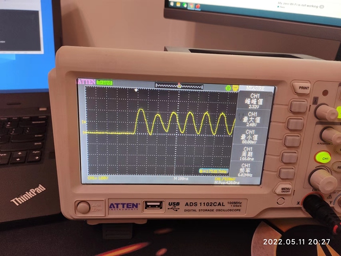
I have a oscilloscope but I’m not very skilled with it. Here is my results.


As you have said ,it only 6MHz.
I try to use spidev but the library will report segmentation fault Error without other messages. so i abandoned the library.
libmraa library Spi Instance writeByte function what each loop write only one byte.so this is another reason why my screen is solw .

The picture aboves is of measuring clock pin

1 Like

just now I’m retry the spidev library, it run the program successful, Turns out I was using it the wrong way.

  • Much faster than before :joy:

Could you please write up a basic step by step on how to get an SPI display working? I have an ST7789V - it it really just as simple as editing the armbianEnv.txt file to include the module and set the appropriate parameters?

You should follow the steps explains here:

What I had not seen was the SECOND PAGE of these instructions. Thank you. Now it makes sense as a narrative.

Unfortunately it still does not make sense as actual instructions. The first page contains a few paragraphs that look like they’re supposed to be instructions, but aren’t actually instructions. They’re statements of information, but the comments above those blocks do not tell you either whether you’re supposed to see that information somewhere and correct it if it’s missing, add it to something, or fix it if it’s not there, or indeed where to put those parameters or that information.

The comments also don’t actually tell you what to do with that information, where the information is supposed to go or come from, or why. It’s not instructions, it’s just disassociated information. You can’t actually follow the steps to achieve goal, because they’re not all steps.

The conceit is that the instructions as written assume that the reader is going to be both familiar and comfortable with compiling their own device drivers and descriptors (as near as I can tell). This is a poor assumption.

Most of us just want the driver support for the most commonly used hardware ready to go, and not have to roll up our sleeves and compile our own drivers. Product engineers are supposed to be doing this, and this should not be an end-user level issue. If this is within your skill set, then hurray, well done - but that’s not most of us.

In the interim, if anybody can translate those data statements into actual instructions, I think the entire community would benefit.

I can confirm that the demo code is working and is clear enough. You must have the necessary knowledge to follow the instruction and build the device tree : basic linux knowledge, bash, etc… you don’t need to be a linux expert but a minimum level is required because it’s not plug and play and you should connect the corrects pins to your device because most devices are specific to Raspberry devices and because the Zero is a rather recent SBC

As a professional technical writer and lead programmer with decades of experience in both, I can confirm that it is not clear enough. Connecting the pins is something anybody can look up, that’s fine. And, I’m sure it’s clear to you. However, I ask you to consider the possibility that more people need to be able to follow this procedure than can necessarily fill in the blanks present in the documentation.

Can you hand these instructions to somebody who has never rebuilt a device tree before and expect them to successfully complete the task? For most people this will be their first exposure to the process.

The answer to “how does this work” should not be “if you don’t surf, don’t start.”