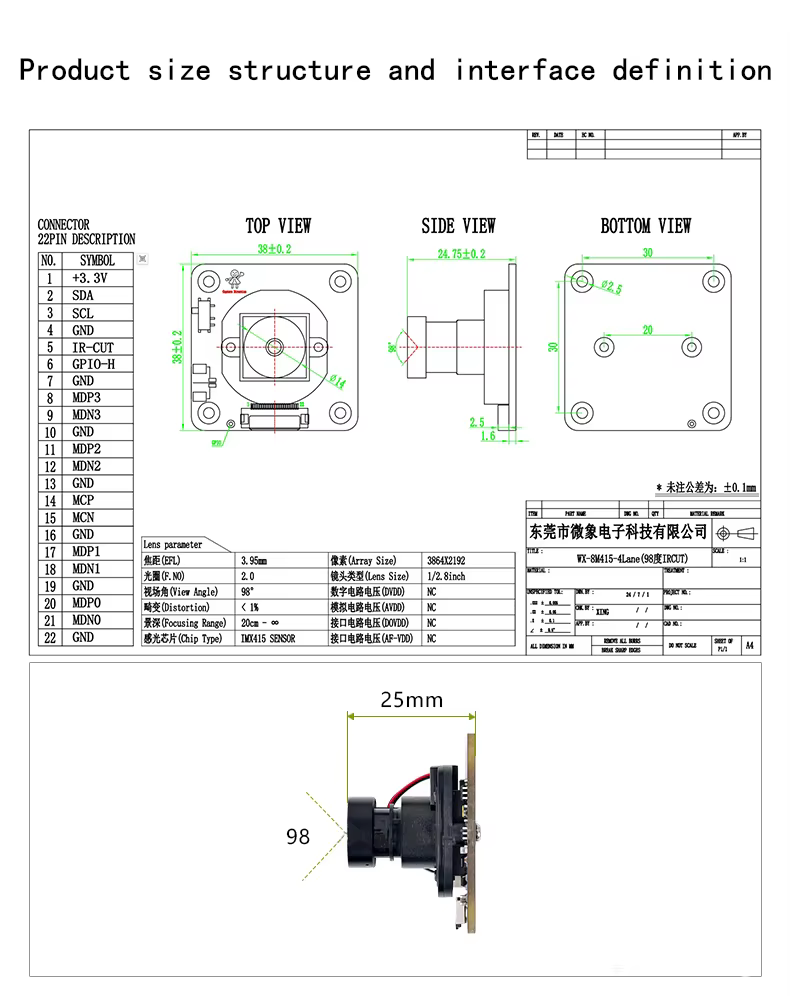
I am doing the same think with kernel 5.10 .Below is the device tree node i am using but log is showing “rockchip-csi2-dphy0: No link between dphy and sensor“ .help me if there is any issure in the dts
imx415_clk: imx415-xclk {
compatible = “fixed-clock”;
#clock-cells = <0>;
clock-frequency = <37125000>;
};
&csi2_dphy0 {
status = “okay”;
ports {
	#address-cells = <1>;
	#size-cells = <0>;
	port@0 {
		reg = <0>;
		#address-cells = <1>;
		#size-cells = <0>;

		mipi_in_cam0: endpoint@0 {
			reg = <0>;
			remote-endpoint = <&imx415_out>;
			data-lanes = <1 2 3 4>;
		};
	};
	port@1 {
		reg = <1>;
		#address-cells = <1>;
		#size-cells = <0>;

		csidphy0_out: endpoint@0 {
			reg = <0>;
			remote-endpoint = <&mipi_csi2_input>;
		};
	};
};
};
&csi2_dphy1 {
status = “disabled”;
};
&csi2_dphy2 {
status = “disabled”;
};
&csi2_dphy_hw {
status = “okay”;
};
&i2c2 {
status = “okay”;
pinctrl-names = “default”;
pinctrl-0 = <&i2c2m1_xfer>;
imx415: imx415@37{
    compatible = "sony,imx415";
    reg = <0x37>;
    status = "okay";

	rockchip,camera-module-index = <0>;
    rockchip,camera-module-facing = "back";
    rockchip,camera-module-name = "imx415";
    rockchip,camera-module-lens-name = "default";

    clocks = <&imx415_clk>;
    clock-names = "inck";

    reset-gpios = <&gpio3 RK_PC6 GPIO_ACTIVE_LOW>;

    avdd-supply = <&vcc3v3_sys>;
    ovdd-supply = <&vcc3v3_sys>;
    dvdd-supply = <&vcc3v3_sys>;

    port {
        imx415_out: endpoint {
            remote-endpoint = <&mipi_in_cam0>;
            data-lanes = <1 2 3 4>;
            link-frequencies = /bits/ 64 <445500000>;
        };
    };
};
};
&mipi_csi2 {
status = “okay”;
ports {
	#address-cells = <1>;
	#size-cells = <0>;

	port@0 {
		reg = <0>;
		#address-cells = <1>;
		#size-cells = <0>;

		mipi_csi2_input: endpoint@1 {
			reg = <1>;
			remote-endpoint = <&csidphy0_out>;
		};
	};

	port@1 {
		reg = <1>;
		#address-cells = <1>;
		#size-cells = <0>;

		mipi_csi2_output: endpoint@0 {
			reg = <0>;
			remote-endpoint = <&cif_mipi2_in0>;
		};
	};
};
};
&rkcif {
status = “okay”;
// memory-region = <&cif_reserved>;
};
&rkcif_mipi_lvds {
status = “okay”;
port {
	cif_mipi2_in0: endpoint {
		remote-endpoint = <&mipi_csi2_output>;
	};
};
};
&rkcif_mipi_lvds_sditf {
status = “disabled”;
};
&rkcif_mmu {
status = “okay”;
};
&rkisp {
status = “disabled”;
};
&rkisp_vir0 {
status = “disabled”;
};
&rkisp_vir1 {
status = “disabled”;
};