I just found that there is a GPIO map now on the wiki but my question is.
Where is the GPIOAO_7 (TDMB_FS) connected to?
GPIOAO_4 (TDMB_D0) and GPIOAO_8 (TDMB_SCLK) seem to be connected to pin 32 and 35
but no word clock on the pins?
1 Like
You can refer to our schematic for this kind of questions.
Regarding GPIOAO_7, you can find it is connected to GPIOA0-7 wire on page 4, which is in turn connected to our power protection IC’s EN pin on page 8.
Since not all I2S related pins are available, we didn’t label them as such in our documentation.
1 Like
Hi,
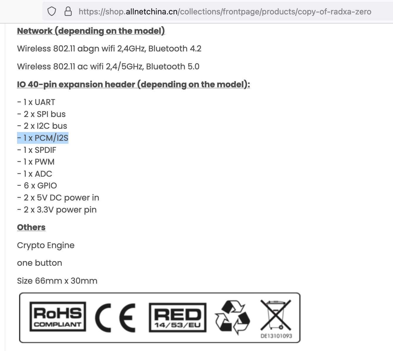
I am very interested in using I2S on the Radxa Zero and I came across this post, showing that TDMB_FS is not wired to the GPIO and is instead being used for the EN pin of the SY6280AAC. Does this mean that it is impossible to use I2S in the Radxa Zero? Or are we supposed to use the TDMA interface to do this? The Radxa Zero advertises that it has a PCM/I2S port, so it would be disappointing if this is false information.
Additionally, I do not believe there is any public datasheet that explains how to enable the TDMA or TDMB, and I would be interested in seeing how this might be possible.
Zero does not support I2S. Please show me where says it does and I’ll have it corrected.
It is listed on this page: https://wiki.radxa.com/Zero/getting_started
It is also listed on distributor websites such as ameriDroid and ALLNET
After further digging on the schematic I found out we indeed routed TDMA port to the 40-pin header so that could be used for I2S/PWM. I’ll update the wiki page to reflect that now. They use GPIOX_8-11.
1 Like
I’m interested in hearing from anyone who has successfully used an I2S component with the Radxa Zero. I’m designing a product and trying to decide whether to use I2S or USB for the audio interface.
@RadxaYuntian @Bedrock @theophile can anyone confirm that I2S is or is not supported on the Zero? And/or which revision?
This is ambiguous to me:
This still appears in the wiki:

As well as official marketing channels:
Can we get an official answer in this thread, perhaps? This thread shows up in google for “radxa zero i2s” along with the sales/marketing info and official wiki.
I am still trying to familiarize myself with the schematic but this is a waste of time if there’s no hope. It seems exponentially beneficial to your customers to simply save them the trouble of developing intimate knowledge of your schematic and the S905Y2 when you could simply omit “I2S” from marketing and docs.
Thanks.
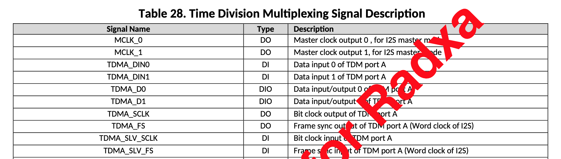
I ended up going a different route for my project so I didn’t test this, but I arrived at the conclusion that I could probably get it to work using an IC that specifically supports TDM. The GPIO pinout shows that pins GPIOX_8, GPIOX_9, GPIOX_10, and GPIOX_11 have available functions of TDMA_D1, TDMA_D0, TDMA_FS, and TDMA_SCLK, respectively. These would need to be enabled/configured with one more more custom nodes in the device tree. It may also be possible to set up I2S over the same interface, but I didn’t go far enough down the rabbit hole to figure it out for sure.
1 Like
Thanks for following up. It sounds like I ended up in the exact same spot which is wondering how to get my external ADC and DAC to speak TDM. I’m afraid to waste any more time on this until I have some official response from Radxa. Thanks again.
The quick reference seems somewhat ambiguous regarding TDM vs I2S. I need access to the full datasheet omg it’s noon here what am I even doing. My theory at this point is that we need the device tree to do the following (this could be very wrong):
- Set (GPIOX_8 to Func2) TDMA_D1 to input mode as I2S DIN
- Set (GPIOX_9 to Func1) TDMA_D0 to output mode as I2S DOUT
- Set (GPIOX_10 to Func1*) TDMA_FS as I2S LRCK
- Set (GPIOX_11 o Func1*) TDMA_SCLK as I2S SCK
*GPIOX_10-11 in “Slave” mode will be Func2. It seems in “Master” mode you’d also need access to MCLK_0 at GPIOAO_9/Func5 which appears to be available on Pin 37 of the 40 pin header.

Adding to the fun is the giant, full opacity, NDA protection yayyy
Saving reference to this here: linux/arch/arm64/boot/dts/amlogic/meson-g12a-radxa-zero.dts at master · torvalds/linux · GitHub
Page 7 of the QR says the SoC has “2 built-in TDM/PCM/I2S ports with TDM/PCM mode up to 384kHz x32bits x 8ch or 96kHz x 32bits x 32ch and I2S mode up to 384kHz x 32bits x 8ch.”
The device tree sets up three TDM audio controllers, tdmif_a, tdmif_b, and tdmif_c. There are also nodes further down for tdmin_* and tdmout_*, as well as toacodec and tohdmitx.
In the Radxa Zero dts, there’s a sound node that I haven’t fully parsed yet, but looks to me like it’s routing audio data from the TDMB interface to the tohdmitx node in i2s format.
It looks like the toacodec driver has functions similar to the tohdmitx driver to output in i2s “format.”
Basically, the existing device tree is already using i2s audio over the HDMI connector using the TDMB pins. The SoC apparently has a second interface capable of i2s audio, it’s just a matter of creating a device tree overlay to enable it on the TDMA interface. Maybe the existing sound node can be used as a template for trying that.
1 Like
Here’s a patch that I stumbled across but can’t find anywhere else, which looks like it implements all possible audio routes on the U200. That board uses the S905D2 chip, which is also in the g12a family.
1 Like
We are now both looking at the same stuff at the same time ![]()
I’ve spent a good half hour today reading Jerome Brunet’s code. Okay thanks. I think it is actually possible, now. I will continue messing with it this weekend if I have time.
I emailed Jerome Brunet from BayLibre who seems to be the authority on Amlogic g12 sound and he very kindly responded! Here is his response (published here with permission) as well as his patch (attached). I think I have converted his patch into a device tree overlay but I’m sure it has errors (also, I haven’t tested it and have no idea what I’m doing).
Response:
You don’t have to “sacrifice” HDMI in any way.
You can add any number of consumer on a TDM link, as long as they cope
with the same link format.HDMI may use any TDM in the SoC, the choice is arbitrary and can be
changed at runtime.To enable 8ch on HDMI, the display controller need 4 lanes of 2ch
i2s interface. Most codecs take a single lane. If you put a codec with
this, it will get the first 2ch only. Because of this, it is best to use
a TDM controller not routed outside for HDMI, since it can’t be used for
anything else.HDMI has been set to use TDMB on your device:
Making sure you're not a bot!It works but it not a great choice. TDMC would be better.
Feel free to contribute if you want to.As far as I can see from the schematics, two TDMs are routed out of the
SoC on this device. TDMA and TDMB. However only one timing interface is
available:
- GPIO AO7 (TDM Frame clock PAD1) is routed to the power supply U8507
- GPIO AO8 (TDM Bit clock PAD1) is routed to LED8
You’ve got:
- Timing interface PAD0 on pins:
- MCLK: GPIOAO_9
- SCLK: GPIOX_10
- LRCLK: GPIOX_11
- Data:
- TDMA: GPIOX_8, GPIOX_9
- TDMB: GPIOAO_4, GPIOAO_10
Attached is an example adding a 2ch i2s on the timing interface and TDMA
GPIOX_8You will still have to use amixer/alsamixer to set the routes at
runtime, depending on your needs.Regards
Jerome
Patch he attached for reference:
0001-arm64-meson-g12a-radxa-zero-add-i2s-on-TDMA-D0.patch.zip (1.9 KB)
I am also attaching my overlay file but it is a work in progress and I have no idea what I’m doing. Any advice would be awesome.
radxa-zero-i2s.dts.zip (1.3 KB)
Very interesting! I wonder why he says TDMC would be a better choice for HDMI audio. I don’t have an i2s audio device but I am using audio over HDMI and am curious whether it’s worth trying to use TDMC instead of TDMB.
I was telling him it was okay if I sacrificed HDMI audio because wasn’t using HDMI at all. I haven’t tried my dto yet mainly because I’ve realized the official Radxa Zero image I used doesn’t have /boot mounted and then the CM3 IO images (neither debian nor ubuntu) don’t have /boot/uEnv.txt. Still trying to figure that out but if I can’t overlay the device tree it’s a bit of a show stopper. I might try Armbian instead. Who knows.
To be very fair to radxa, the official “how to make I2S work” thread on the raspberry pi forums spans 10 years and over 1000 posts.
I was referring to this comment
Re-reading his email, I think I understand what he meant. He said earlier that “it is best to use a TDM controller not routed outside for HDMI, since it can’t be used for anything else,” and then later that “two TDMs are routed out of the
SoC on this device. TDMA and TDMB.” So I think he meant that TDMC would be a better choice for HDMI because that leaves the other two TDM controllers (A and B) available for other uses. Currently, using TDMB for HDMI audio prevents TDMB from being used for anything else while at the same time leaving TDMC unable to be used at all because it’s not routed out of the SoC at all.
That’s a fair point, as TDMB_D0, TDMB_D1, TDMB_D3, and TDMB_SCLK are on pins GPIOAO_4, GPIOAO_10, GPIOH_5, and GPIOAO_8, respectively, all of which are in the 40-pin gpio header. On the other hand, TDMB_FS is on GPIOAO_7, which is not in the gpio header. I don’t know enough about the TDM/I2S interface to know whether TDMB is usable without access to that pin.
Regarding the overlay, if your distro is using extlinux, you can add device tree overlays like this.
I have no idea if my distro is using extlinux. I just flashed the sd cards with the images marked “official” on the download pages. I will try to research this. It was a total bummer because yesterday I was all excited that I might have working a dtbo for both the zero and the cm3 and then couldn’t do anything because there was no obvious way to apply my dtbo from the tree. All the wiki docs seemed to point to images I wasn’t using. I just don’t understand where those images are available.
https://wiki.radxa.com/Device-tree-overlays
/boot/uEnv.txt contents:
Uhh. Am I supposed to make that file or is it already supposed to be there? When I reference a dtbo with overlays= where are those overlays supposed to be? /boot/overlays?
I have /boot/config.txt. I can’t find out anything about what goes in there on the radxa wiki. Yet, again, I only used “official” radxa images. Debian nor ubunto had /boot/uEnv.txt
I definitely have /boot/dtbs/$(uname -r)/rockchip/overlay/
What’s in /boot/config.txt? That’s probably the file you want.