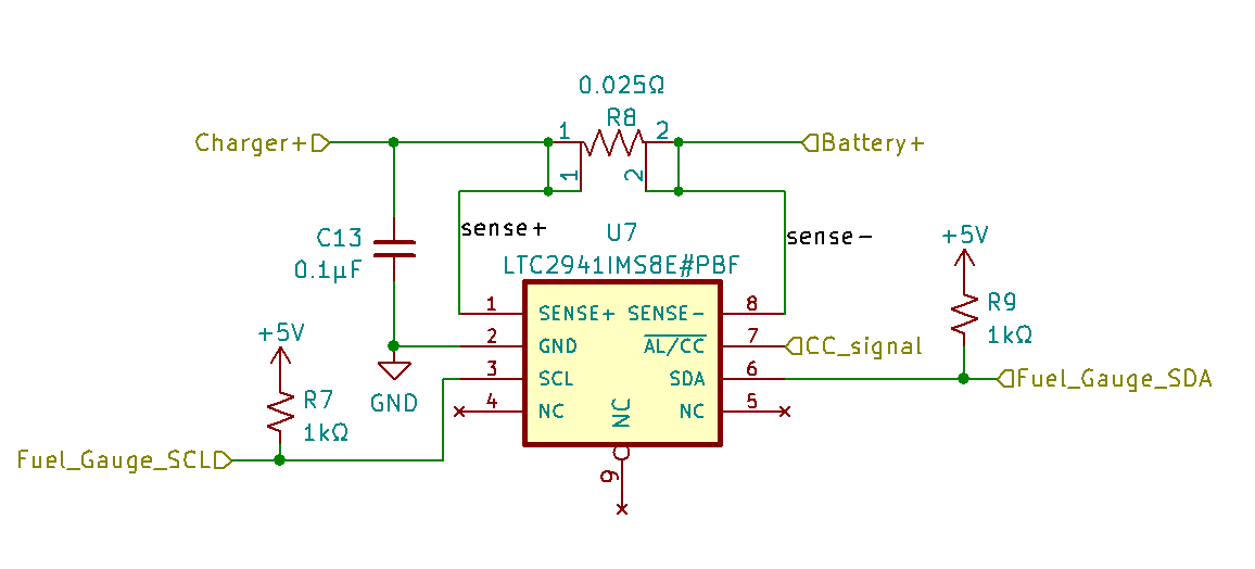
Sure do. Here’s the schematic of the fuel gauge subcircuit:
The IC is the LTC2941. I used the MSOPO-8 package for ease of hand soldering. There’s also a 25 mΩ current sense resistor. If memory serves, this is just the typical application circuit straight from the datasheet.
You’ll see the yellow flags indicating how it fits into the rest of the circuit. At the top there’s Charger+ on the left and Battery+ on the right. These contact points basically sit between the positive terminal of the battery and whatever point on the charger the positive battery terminal would normally connect to. Then on the bottom there’s Fuel_Gauge_SCL on the left and Fuel_Gauge_SDA on the right. These are just the two i2c data lines that connect to SCL and SDA on the Radxa Zero GPIO header.
In my case I used i2c3 on pins 3 and 5. I have a device tree overlay for the LTC2941 here. I’m sorry it’s in patch format, but the important bits are at the bottom of the file and you could easily copy these into a clean .dts file.
