Debug Rock5b/rk3588 with SWD/JTAG

Has someone managed to connect a hardware debugger to SWD/JTAG (2 pins: TMS/TCK) on a rock5b rk3588 with openocd? I have been struggling to set this up properly, My openocd always fails to establish a connection to the target.

I connected JTAG_TCK_M0 to Pin 9 on a Arm JTag-20 connector, JTAG_TMS_M0 to Pin 7. And VSS to ground. I am using an sdcard adapter breakout to expose the pins [0].
force_tag is enabled (default), gpio4_d2_sel is 0x1, gpio4_d3_sel is 0x1 (default).

Despite this, i fail to make any connection to the device. The device is in uboot bl33 boot menu when i connect the probe.

Some more context:
Hardware Debugger: Olimex ARM-USB-TINY-H
Openocd configuration as a starting point: https://pastebin.com/7MrbQm08

[0] https://www.aliexpress.us/item/1005006267829221.html?spm=a2g0o.order_list.order_list_main.149.3b5d5c5fWln5Pd&gatewayAdapt=4itemAdapt

image

TRM: https://github.com/FanX-Tek/rk3588-TRM-and-Datasheet/blob/master/Rockchip%20RK3588%20TRM%20V1.0-Part1-20220309.pdf

Regarding your configuration, you want to change 0x81010000. Core 0 -dbgbase is at 0x81004000 and its CTI at 0x81014000. Add 0x1000 to each for core 1 to 7.

Make sure you do not boot from an SD card as doing so will reconfigure the “Pin mux” to move the SWD pins away from the shared SD pins. You can test SWD connection by holding the golden button for MaskROM mode (check https://wiki.radxa.com/Rock5/install/usb-install-emmc for a photo), and then power on the Rock 5B. You will be able to connect to SWD with Open OCD and confirm your wiring + software setup is correct. Forcing MaskROM mode by clearing the eMMC/SPI will not work because the ROM will enumerate the SD card and disable SWD.

In my experience, I was never able to make “force_tag” work as claimed (i.e. SWD is enabled after some inactivity time on the SD). It is possible that the binary blob BL31 is disabling this bit somehow, I haven’t checked. I found it easier to just do the below.

You can rebuild the bootloaders for the Rock 5 boards to not initialise the SD hardware and let you SWD into a running system. You want to:

  1. In the u-boot source tree for your device, remove all references to “fe2c0000” (usually in mmcX nodes) and “sdmmc”.
  2. Recompile the bootloader
  3. Flash the new boot image
  4. Profit

If you want to SWD Linux, you can check if the device tree binary is available via the file system and if it is, you can just edit out sdmmc/fe2c0000 without recompiling the kernel.

Thank you for your reply.

Booting the board into maskrom mode does not change the connection issue.

I am still receiving: Error connecting DP: cannot read IDR.

This would make me conclude that there must be a physical connection issue, if you manage to receive a connection from maskrom mode.

  1. (Detour) What version of openocd do you use? In the latest version there is no -ctibase option in target create.
For bug reports, read
	http://openocd.org/doc/doxygen/bugs.html
Info : FTDI SWD mode enabled
DEPRECATED! use 'adapter speed' not 'adapter_khz'
Warn : Transport "swd" was already selected
./rk3328.cfg:16: Error: Unknown param: -ctibase, try one of: -type, -event, -work-area-virt, -work-area-phys, -work-area-size, -work-area-backup, -endian, -coreid, -chain-position, -dbgbase, -rtos, -defer-examine, -gdb-port, or -gdb-max-connections
in procedure 'script' 
at file "embedded:startup.tcl", line 28
at file "./rk3328.cfg", line 16


maskrom mode:

sudo rkdeveloptool ld
DevNo=1 Vid=0x2207,Pid=0x350b,LocationID=104 Maskrom

openocd connection issue:

sudo openocd -f ./olimex-arm-usb-tiny-h2.cfg -f ./rk3328.cfg
Open On-Chip Debugger 0.12.0-01004-g9ea7f3d64 (2024-12-27-21:22)
Licensed under GNU GPL v2
For bug reports, read
	http://openocd.org/doc/doxygen/bugs.html
Info : FTDI SWD mode enabled
DEPRECATED! use 'adapter speed' not 'adapter_khz'
Warn : Transport "swd" was already selected
Info : Listening on port 6666 for tcl connections
Info : Listening on port 4444 for telnet connections
Info : clock speed 4000 kHz
Error: Error connecting DP: cannot read IDR

target.cfg:

#
# Rock-Chip RK3328
#

adapter_khz 4000
transport select swd

set _CHIPNAME rk3328
set _TARGETNAME $_CHIPNAME.cpu

set _ENDIAN little

swd newdap $_CHIPNAME cpu none
dap create $_CHIPNAME.dap -chain-position $_CHIPNAME.cpu

target create ${_TARGETNAME}0 cortex_a -dap $_CHIPNAME.dap \
    -coreid 0 -dbgbase 0x81040000
#  -ctibase 0x81014000

#
target smp ${_TARGETNAME}0

${_TARGETNAME}0 configure -event reset-assert-post "cortex_a dbginit"

debugger.cfg:

# SPDX-License-Identifier: GPL-2.0-or-later

#
# Olimex ARM-USB-TINY-H
#
# http://www.olimex.com/dev/arm-usb-tiny-h.html
#

adapter driver ftdi
transport select swd

ftdi device_desc "Olimex OpenOCD JTAG ARM-USB-TINY-H"
ftdi vid_pid 0x15ba 0x002a

ftdi layout_init 0x0808 0x0a1b
ftdi layout_signal nSRST -oe 0x0200
ftdi layout_signal nTRST -data 0x0100 -oe 0x0100
ftdi layout_signal LED -data 0x0800

# Map FTDI GPIO pins for SWD
ftdi layout_signal SWCLK -data 0x0100 -oe 0x0100
ftdi layout_signal SWDIO -data 0x0200 -oe 0x0200


ftdi layout_signal SWD_EN -data 0x0000 -oe 0x0000

lsusb:

Bus 001 Device 005: ID 15ba:002a Olimex Ltd. ARM-USB-TINY-H JTAG interface

dmsg:

[190208.771978] usb 1-6: new high-speed USB device number 5 using xhci_hcd
[190208.903042] usb 1-6: New USB device found, idVendor=15ba, idProduct=002a, bcdDevice= 7.00
[190208.903054] usb 1-6: New USB device strings: Mfr=1, Product=2, SerialNumber=3
[190208.903064] usb 1-6: Product: Olimex OpenOCD JTAG ARM-USB-TINY-H
[190208.903068] usb 1-6: SerialNumber: OL44653F
[190208.912563] ftdi_sio 1-6:1.1: FTDI USB Serial Device converter detected
[190208.912644] usb 1-6: Detected FT2232H
[190208.912846] usb 1-6: FTDI USB Serial Device converter now attached to ttyUSB0

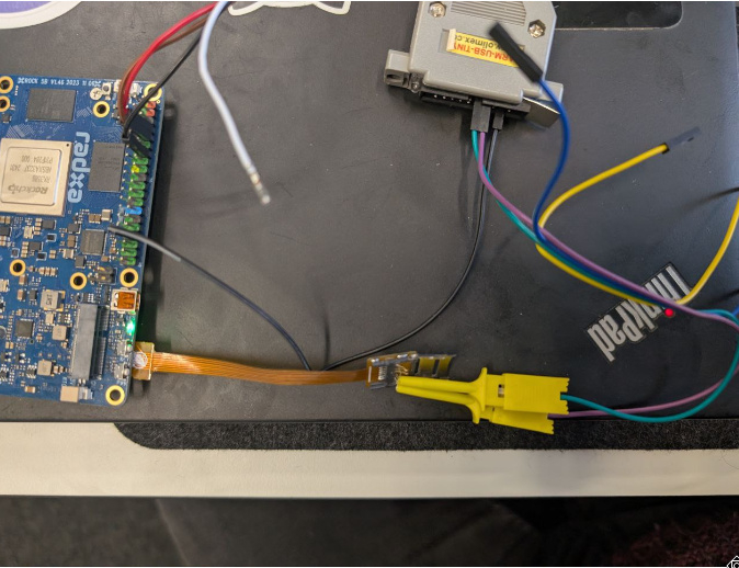
  1. For the wiring. I currently do not have a multi meter. But it is only 3 pins I am connecting.

Let me walk you through my steps, maybe you have some idea what I forgot.

image

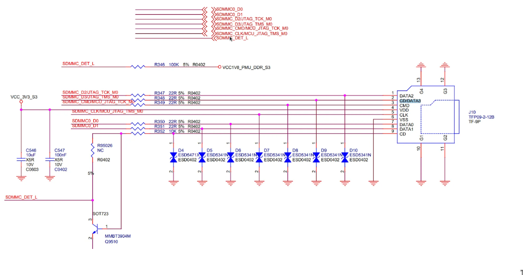
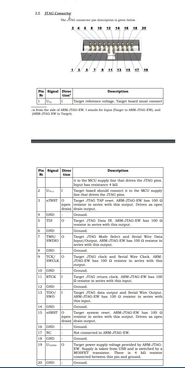
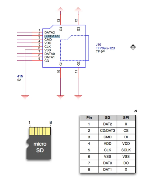
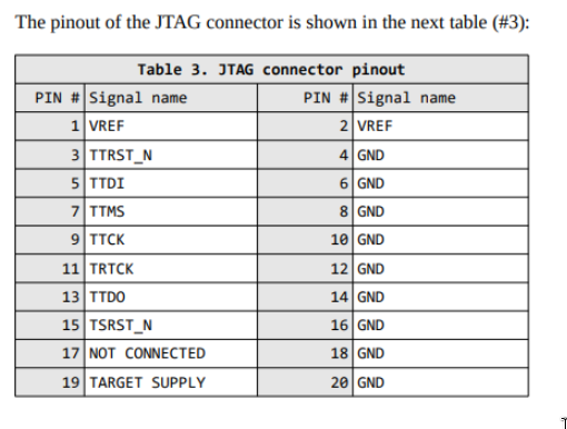
  • Sdcard Pin1: Data2 -> SDMMC_D2/JTAG_TCK_M0 -> TTCK on jtag connector -> Pin 9

  • Sdcard Pin2: CD/Data3 -> SDMMC_D3/JTAG_TMS_M0 -> TTMS on jtag connector -> Pin 7

  • Connect GPIO ground pin on board with any ground pin on the JTAG connector

Do you have some ideas? Or perhaps a working configuration for your setup you can point me to?

Any help is greatly appreciated.

I cannot help you with the Olimex part as I use both a J-Link Edu and ST-Link V2 (chinese V2 clone works fine) and V3 (official).

Just to confirm, make sure you force maskrom mode with the gold button. If that doesn’t work for you, then your wiring is probably not correct.

Here’s my partial config, I use recent OpenOCD (0.12 and later):

if { [info exists CHIPNAME] } {
  set _CHIPNAME $CHIPNAME
} else {
  set _CHIPNAME rk3588
}

adapter speed 4000
transport select swd
# transport select dapdirect_swd // Use this for stlink v2

source [find target/swj-dp.tcl]

# declare the one SWD tap to access the DAP
swd newdap $_CHIPNAME cpu -ignore-version

# create the DAP
dap create $_CHIPNAME.dap -chain-position $_CHIPNAME.cpu
target create $_CHIPNAME.ahb mem_ap -dap $_CHIPNAME.dap -ap-num 0

# declare the 4 main application cores
set _TARGETNAME $_CHIPNAME.core
set _smp_command ""

set $_TARGETNAME.base(0) 0x81004000
set $_TARGETNAME.base(1) 0x81005000
set $_TARGETNAME.base(2) 0x81006000
set $_TARGETNAME.base(3) 0x81007000
set $_TARGETNAME.base(4) 0x81024000
set $_TARGETNAME.base(5) 0x81025000
set $_TARGETNAME.base(6) 0x81026000
set $_TARGETNAME.base(7) 0x81027000

set $_TARGETNAME.cti(0) 0x81014000
set $_TARGETNAME.cti(1) 0x81015000
set $_TARGETNAME.cti(2) 0x81016000
set $_TARGETNAME.cti(3) 0x81017000
set $_TARGETNAME.cti(4) 0x81034000
set $_TARGETNAME.cti(5) 0x81035000
set $_TARGETNAME.cti(6) 0x81036000
set $_TARGETNAME.cti(7) 0x81037000

set _cores 8
for { set _core 0 } { $_core < $_cores } { incr _core 1 } {
    cti create cti$_core -dap $_CHIPNAME.dap -baseaddr [set $_TARGETNAME.cti($_core)] -ap-num 0
    set _command "target create ${_TARGETNAME}$_core aarch64 -dap $_CHIPNAME.dap -coreid $_core -cti cti$_core -dbgbase [set $_TARGETNAME.base($_core)] -work-area-size 0x100000 -work-area-phys 0xFF000000 -work-area-backup 0"

    if { $_core != 0 } {
        set _smp_command "$_smp_command ${_TARGETNAME}$_core"
        set _command "$_command -defer-examine"
    } else {
        set _smp_command "target smp ${_TARGETNAME}$_core"
    }

    eval $_command
}

eval $_smp_command

${_TARGETNAME}0 configure -event reset-assert-post "aarch64 dbginit"
${_TARGETNAME}1 configure -event reset-assert-post "aarch64 dbginit"
${_TARGETNAME}2 configure -event reset-assert-post "aarch64 dbginit"
${_TARGETNAME}3 configure -event reset-assert-post "aarch64 dbginit"
${_TARGETNAME}4 configure -event reset-assert-post "aarch64 dbginit"
${_TARGETNAME}5 configure -event reset-assert-post "aarch64 dbginit"
${_TARGETNAME}6 configure -event reset-assert-post "aarch64 dbginit"
${_TARGETNAME}7 configure -event reset-assert-post "aarch64 dbginit"

You should also check if your JTAG dongle has and/or needs a VREF (connected to SD 3.3v). Some dongles need it (e.g. J-Link will complain if it senses 0v and is not guaranteed to work in this state). ST-Link v3 was similar if I remember right.

Worth a shot: you could try swapping the IO vs CLK configs in the Olimex config in case they’re the other way around.

Thanks. After more try and error I figured it out. The issue was the Olimex itself. I managed to connect SWD with an old raspberry pi used as debugger.

Just out of curiosity, have you ever implemented a software based device reset for the rk3588? U-boot supports device reset with the reset command. I think I will look into how to reset the rk3588 using gdb/openocd with a software based reset hook.

You can write to 2 registers in the CRU to trigger a reset. They are GLB_SRST_FST_VALUE and GLB_SRST_SND_VALUE:

In OpenOCD, you would use 2x “mww 0xXXXXXXXX 0xYYYYYYYY” to do the writes.

Thanks, awesome. Many thanks! If I already have you here, could you also share your sample debug setup/workflow with me for rk3588? I saw you created rk3588-svd. Do you use plain openocd/gdb or another setup? In what setup do you personally debug with the rk3588.svd file?

So far I resorted to printf. But a more advanced debug setup could save me much time.

I use “ARM Development Studio” for SVD because it does a great job at showing registers. See attached screenshot. Last time I checked though, the hobby license didn’t allow using aarch64 in projects or the debugger.

For general debugging, you can use gdb based debuggers. Using regular GDB, you can do for example:

  1. openocd -f …
  2. aarch64-xxx-gdb
  3. target remote localhost:4444

At this point, gdb will have halted the RK3588 device and it is ready to debug.
You could also pass an ELF file to the gdb command line to get symbols during debugging.

I know there are SVD plugins for GDB but I have not tried them myself: https://github.com/ccalmels/gdb-dashboard-svd

You could also look at https://probe.rs, they claim to support VSCode integration for debugging, and there are SVD plugins for VSCode.

You could also write your own TCL scripts that you invoke directly from OpenOCD over telnet. In these scripts, you can do fancy stuff like (in pseudo code) "if register_XXX & flag == whatever then dump reg_YYY else reg_ZZZ). I do that for some use cases that I’m using. The scripts go directly in the .cfg you pass to OpenOCD.

Great to hear that an RPi can work as a debug tool! I have an RK3588 I’d like to JTAG straight from MaskROM . So I’m curious if you could share your RPi setup and full OpenOCD configuration for the RK3588? I assume the top of the configuration looks something like this?

adapter driver bcm2835gpio
#SWD pins
bcm2835gpio_swd_nums 24 25
transport select swd
#400khz baud
adapter speed 4000

Sorry for my delayed response. the RPi setup is from one of the first google results – openocd supports it out of the box.

 rp3.cfg:
# rpi2.cfg: OpenOCD interface on RPi v2+

# Use RPi GPIO pins
interface bcm2835gpio

# Base address of I/O port
bcm2835gpio_peripheral_base 0x3F000000

# Clock scaling
bcm2835gpio_speed_coeffs 146203 36

# SWD                swclk swdio
# Header pin numbers 22    18
bcm2835gpio_swd_nums 25    24

# JTAG                tck tms tdi tdo
# Header pin numbers  22  18  16  15 
bcm2835gpio_jtag_nums 25  24  23  22