as titled,thanks
Could zero 3w use raspi zero ups?pls help
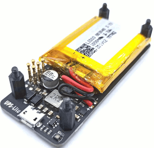
I received a UPS lite v1.2 today and plan to use it on zero 3W.
I’m not entirely confident if possible, but it would be cool.
I have a basic hardware understanding and a few questions got me on hold before trying it.
Let’s see if you the hw guys can give some help.
Here is the UPS:
A few questions:
-
Is the output current enough for board + camera + NPU (performance governor) + Wifi?:
Max 1.3A@5V (only powered by battery without external power supply)
I have a “Kill a WATT” here but it’s old and a bit unreliable for measuring current, if anyone can
measure it accurately that would be good. -
I have not found the 3W pinout diagram, so i am basing it on the Zero, the pins# seems to be 3,5,7
and 4,6. I guess i2c3 should be enabled. Not sure. i2c3 is already in use by fusb302. Which i2c
should be enabled? If not pin to pin compatible i don’t mind wiring it with dupont.
I just need to know the correct pins.
Raspi port is I2C1 which port would be on 3W? -
quoting the doc
“UPS-Lite has an external
power adapter insertion detection function. You can judge whether the external
power supply is inserted by the high and low levels of the GPIO port. When the
power supply is plugged in, the io4 (BCM mode) of the pi will detect a high level.
When unplugging ,the pi will detect a low level, to enable the detection function,
the two pads on the back of the UPS must be shorted, and the GPIO is set to the
floating input state. If the pad is not shorted, the state of the GPIO detection is
unstable”
It says the io4 (BCM mode), but i have no idea what BCM mode is.
I found this Tip for zero 3w:
Pin 3, Pin 5, Pin 27, and Pin 28 add extra pull-up resistors for I2C device power supply, so they work abnormally when used as GPIOs.
I guess we need to decode this sentence…
I forgot to mention, pin3 and pin 5 are (according to doc):
UART3_RX_M0|GPIO1_A0 -> 3
UART3_TX_M0|GPIO1_A1 -> 5
while pin 27 and pin 28 are I2C4.
Hello, any update on this? Share with me with possible…thanks!!
any updates here? I need a ups compatible with radxa zero 3w
