why the silkscreen JLCJLCJLCJLC?
just courius
PCBs ordered from JLCPCB will have an order number, putting JLCJLCJLCJLC indicates the position you specifically wants them to put the order number in.
1 Like
that makes sense
and i have a pcb that says JLCJLCJLCJLCJLC (from an 16 bit parallel lcd) that wasnt replaced by the order number, wierd
I paid to remove it
They might have mistakenly used JLC 5 times which should be just “JLCJLCJLCJLC”, No more or less characters
that is possible or three times i think
4K camera is back in stock.
1 Like
Ty for the info ![]()
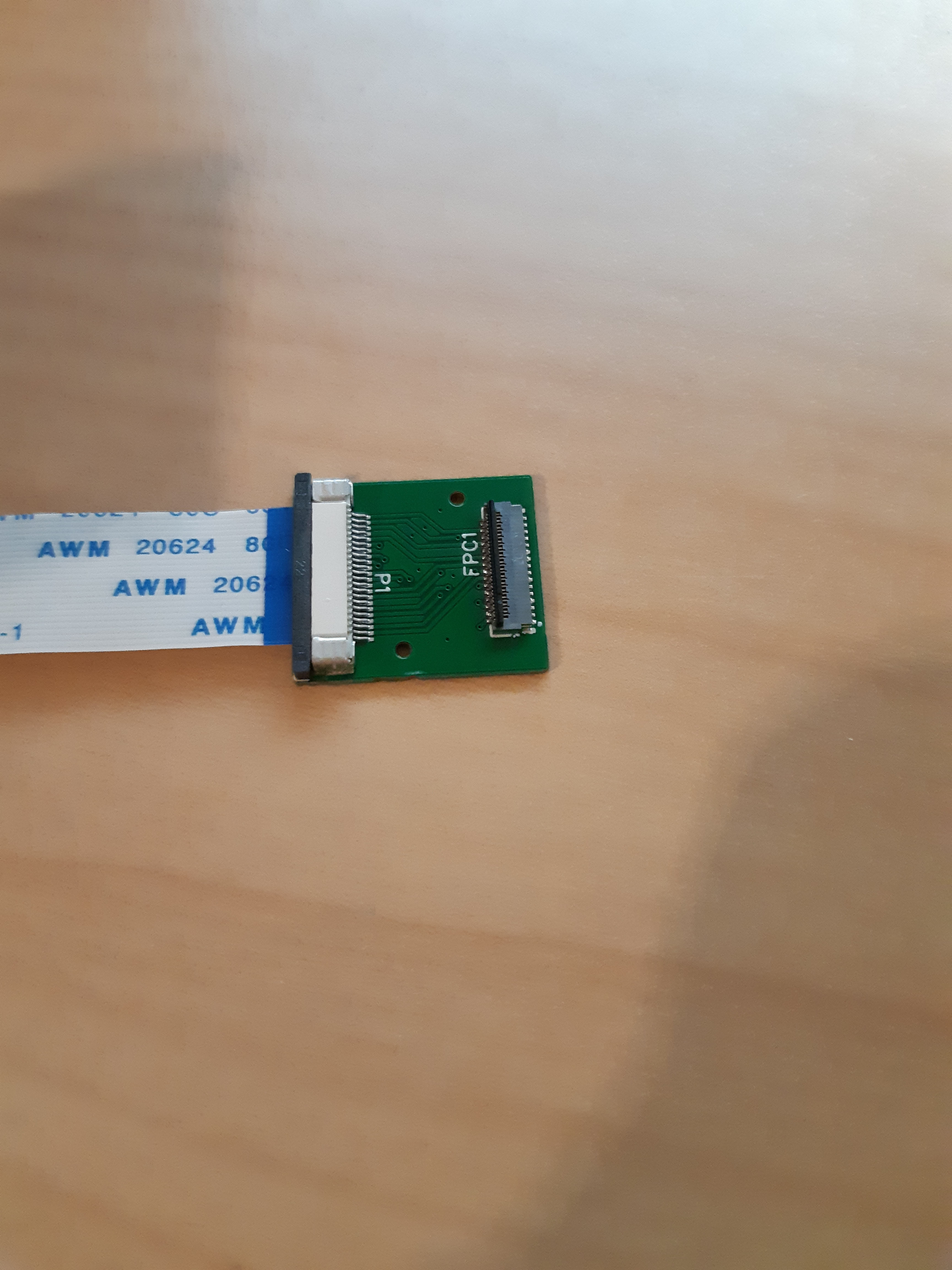
The boards are here. I haven’t received the other ribbon cable yet. JLC seems to have added holes, interesting.
2 Likes
Maybe the IMX577 driver can be modified. They are very similar chips.
The IMX577 can do a few extra things:
- MIPI ULPS operation in power save mode
- Horizontal Low Power Analog Cropping
- Window Scanning mode
Other than that, the product information sheets are more or less identical.
1 Like
Wow! looks great.
How many adapters do you have with you? Do you mind selling one and get it shipped to Canada? Cant wait to test it out!
I have 5. But shipping will probably cost way more than the thing is worth (€10.30). Due to regulation you’re not allowed to ship goods as letters anymore.
That would be a big problem.
Do you mind sharing which exactly is the pcb file you used for those boards and shares what are the parameters you have chosen in JLCPCB, so that we can get them ordered and shipped from China? (I might be able to get some shipped by Hong Kong Post to other countries by letter, which should be much much less than €10)
I mean you’re still allowed to ship them in a letter, but you have to ship them as a letterbox parcel.
I used PCB called “new” (link in first post). Download the gerber files, BOM, and pick and PickAndPlace file. JLC will do everything for you.
1 Like
Is this adapter a 2-layer PCB? I just checked, and the “new” file is a 2-layer board, and the 4-layer board seems incomplete.
Cheapest option to ship from JLC to Canada seems to cost $3.7 USD (10-18 business days)
Yes I ordered the 2 layer one.
Hello,
I can help with MIPI layout if that is needed. I’ve done this before. Length matching between lanes is important, and generally 4 layers are needed for differential stripline.
However, I know less about the driver updates needed to support the IMX477.
Has there been any progress?
I’m interested in building a PoE H.265 network camera with my Rock5B and an HQ camera.
I can help with MIPI layout if that is needed. I’ve done this before. Length matching between lanes is important, and generally 4 layers are needed for differential stripline.
Go ahead. Check out the oshwlab page I linked. I can’t guarantee that the schematic itself is fully correct. The connections of the RPi camera are a little different than the Radxa camera, I tried my best to match them, but there’s some non-connected pins left. The camera connector on the Rock5B has two I2C lines, two PDN lines, and two CLK lines, obviously to accommodate two cameras. I’m reasonably confident about my I2C and CLK connections, but I’m not so sure about the other ones.
However, I know less about the driver updates needed to support the IMX477.
Has there been any progress?
Nothing has changed as far as I know. We need a kernel dev to work on it. And that’s just the kernel part, there’s also image processing that needs to be done.
Yes, also check out my oshwlab which I made a dual camera adapter (not tested tho) thanks!
*The latest file to look at is : Adapter_4layer_mini_WIP
You are probably going to have to add some active components to this board to get it to work with Raspberry Pi cameras.
I’m working on doing something similar for the Orange Pi 5 (which unfortunately opted to use a painfully tiny 0.4mm SMT connector). The RPi boards use 3.3V I/O, including for the I2C and GPIO used for the camera connectors. Consistent with that, at least one camera schematic (for v2 camera) showed an onboard 3.0V regulator for DOVDD.
However, the Rock 5B is using only 1.8v I/O for those signals. For example, on page 15 of the Rock 5B schematic, the VCCIO1 domain, which provides the camera I2C signals (pins G27 and G39), is set to 1.8V and these signals also have pull-up resistors to 1.8V. The OPi5 is the same. You might get lucky and have the camera module interpret 1.8V logic signals correctly, but you’ll likely run into it not working at all or not working sometimes.
So, you can do one of several things to address this:
- Identify the DOVDD regulator on the camera module, and swap in a 1.8V regulator. This probably works for most of the Omnivision cameras. I don’t know about the Sony cameras.
- Add a couple of level translator ICs to the adaptor board. There are even I2C specific translators that handle the bidirectional signaling and high Z states for SDA. You will likely need to send 1.8V power to your adapter board, or also add a little 1.8V regular to your board.
- Route a few of the 3.3V logic level signals from the GPIO connector to the adapter board, such as pins 3 and 5 for I2C. You’ll have to revise the device tree accordingly, since you’ll be changing the I2C device and GPIO. You also end up with two sets of wires going between the Rock 5B and your board. One possible plus is that you likely can take the already made adapter board and rework it by cutting a few traces and soldering on wires for the GPIO connector.
Since I was stuck needing to make a PCB anyway, I’ve opted for number 2. Just sent the PCB design off to OSH Park, with fingers crossed that I’ve got all my pinouts correct. Unfortunately, given the difference in connectors, my board is not useful for the Rock 5B.
FWIW, differential length matching is pretty easy in KiCAD 7. The feature was there in earlier releases, but the trace length calculations were buggy and not fixed until 7.0 rc1. Each differential trace pair must be very closely matched (0.15mm) to each other - dealt with by the differential skew menu item. Then the three (or five for 4 lanes) pairs need to be the same lengths - there is a menu item for hitting a target length. Finally, you need to work out the width and spacing for the pairs of traces to have 100 ohm impedance - there are calculators for this. A four layer board is pretty much mandatory to have controlled impedance. Only thing that was a pain was rerouting trace pairs - KiCAD doesn’t treat them as a unit when pushing traces around.
Good luck!