I’m trying to build a carrier board for the CM5 but I’m struggling to determine the orientation of the ‘extra’ 100-pin board-to-board header.
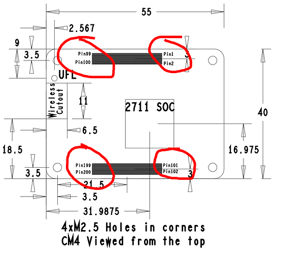
Raspberry Pi labels the pins at each corner of their CM4 connectors:
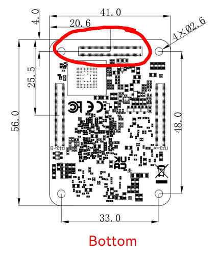
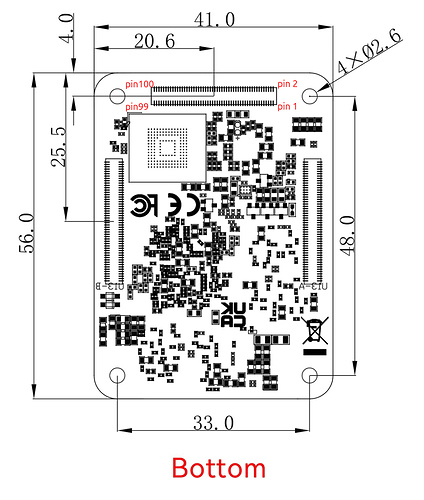
I’d expect to see something similar for the Radxa CM5:
I tried looking at the CM4IO board CAD files but I don’t have Altium and they won’t load in Altium’s online viewer.
Does anyone know where pin 1 is on the third b2b connector?


