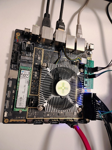
The ATX PSU that I have run to the 24-pin on my Rock 5 is always on. The LED on the board and the PSU fan. Is this normal even when the computer has been shut down?
ATX PSU always on
I’ve just received my Rock 5 ITX and it has the same issue. The ATX PSU isn’t shutdown when the ITX board is powered down. I don’t think this is the correct behaviour.
Worryingly, my ITX board doesn’t have any HDMI output either. Just a blue LED and fan spin.
It seems that the ATX power always being on might actually be normal but I’m not sure.
The early incarnations of this board had a BIOS battery but they changed to an RTC slot on the current version. They don’t ship with an RTC (its left empty) although you can buy one. The Rock 5 has to have some power from somewhere to maintain a few settings like the date and time so I’d guess that’s why the LED and fan are always on. That might also be part of the function of the firmware as the pros will be doing weird stuff shorting pins and so on to make it do other advanced things.
Mine also had no output when it arrived. Just LED & fan spin in the PSU and the CPU heatsink fan.
I’ve seen YouTubers with this board reporting that the eMMC isn’t configured or is blank. I just can’t get
mine to boot into ROOBI from the eMMC.
You can buy a tiny microSD to USB device and use Balena Etcher to write an OS onto the microSD.
The performance with a decent microSD was very good. It felt responsive and in no way hobbled.
You can also get external NVMe to USB device pretty cheap and do what I did which was write the radxaOS onto an NVMe with a Windows PC and then transplant it so see if the NVMe boots on the Rock 5 board.
I have a v1.12 board that has a bios battery holder. I would expect the ATX supply to be off when the ITX board is powered down.
My eMMC was indeed blank. I created an SD card and wrote roobi to eMMC and my board now boots roobi. Armbian is now installed on NVMe to test things function as they should.
Is there a way to modify the ITX board to make it power down fully?
If I’m powering the ITX via a PICOATX supply and 12V AGM battery UPS, and the AGM battery controller decides that battery is depleted and the ITX must shut down I need it to power down completely to prevent killing batteries.
I can partially answer my own question.
A 0R resistor is pulling ATXPWR1.16 to GND which turns on the ATX supply. Power_good appears only used to illuminate a blue LED.
Can the RK806 be powered from 5V_Standby and used to control the ATXPWR1.16?
Yeah, from the schematics at https://dl.radxa.com/rock5/5itx/v1110/radxa_rock_5itx_v1110_schematic.pdf and observation, the board is not following the whole ATX signaling protocol here, and it will never turn the PSU off.
The whole thing is powered from a single 12V rail/input (see block diagram in the third page of the schematics) and the other voltages are converted out of that, so there’s little point in doing anything with the power good signal given the PMIC is already monitoring the 12V input for good conditions before starting everything else, and the system will be started as power is applied.
But it’s still a bummer to have the PSU running when the system powers down.
A possible approach to fixing this that doesn’t require board modifications would involve splicing a number of signals (e.g.: get a 24 pin ATX extender cable, a 4-pin fan extender cable and some male-to-female dupont extension cables for the power switch).
You could do the following:
- Cut ATX pin 16 in the extender, and control it from a microcontroller on the side going towards the PSU. If you’re using a 5V MCU you can just connect it directly; you’d need a transistor otherwise to drive it to GND when you want the MCU to turn the PSU.
- Power the MCU from GND and 5V_Standby spliced from the extender.
- Splice the 12V power from the fan connector: this is turned off when the PMIC shut downs the system. Use a voltage divider or a transistor to provide an input suitable to your MCU. When this voltage goes down for a second or so after having been high before, the MCU can turn off the PSU.
- Splice the power switch from the front panel connector. When the switch is connected to ground, use a diode to bring down a pull-up-enabled input of your MCU. When that is detected, it’s time to turn on the PSU.
While this is complicated, as said before, the good thing is that you can do it without having to make any permanent change to the board.
rock5itx designed the ATX power supply to be continuously powered, and it won’t lose power when you turn it off.
I live in a rural area and mains power loss is not uncommon. Everything of importance here has a UPS to deal with common brief outages. If an outage is prolonged and the UPS batteries get low the various boards are signalled to fully shutdown to prevent the batteries being completely drained.
I thought the low power consumption of the Radxa ITX would be useful in extending UPS uptime, which it will, but at the expense of batteries in its unmodified state.
It sure is. I wasn’t expecting ACPI but I did expect standard power control.
Not complicated at all.  Your input is very helpful.
I have been thinking along similar lines. I’ll put something together to make it work.
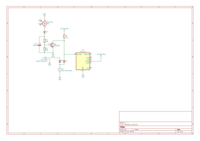
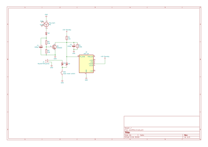
I was thinking that something like this, with a bunch of discrete components would actually do, and you don’t need a microcontroller at all.
It’s not perfect, because if you lose external power, it doesn’t remember the power on/off state before the power loss, and the device will stay off until you press the power on button. A microcontroller that can store the last state in flash might be a better solution in that case.
I’ll test experimentally whether the power on switch header and my PSU’s PS_ON input work when putting a diode in the path to ground…
To avoid the diode drop an n jfet could be used in place of D2. Use -12v on gate to isolate once powered up perhaps?
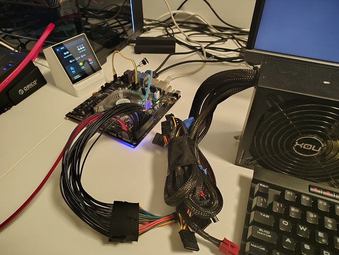
So I made it work more or less as I expected with this final approach:
(Not sure what the best way to share a video here is).
If I power it off and then switch off AC from the PSU, it takes >30s for the capacitor to discharge (at which point it “forgets” the system was off). So the system will always come back on after a long enough loss of power, no matter what the previous state was.
This is probably enough for my needs.
It should be easy though (and even use fewer components) to use a PIC12F675 and a handful of resistors, and it could “remember” the last state in its EEPROM when power comes back.
 Way better than having no power control.
Thanks for the details.
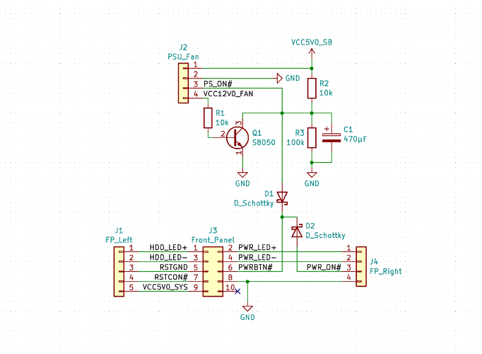
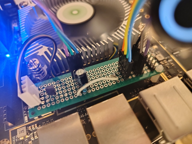
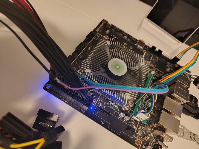
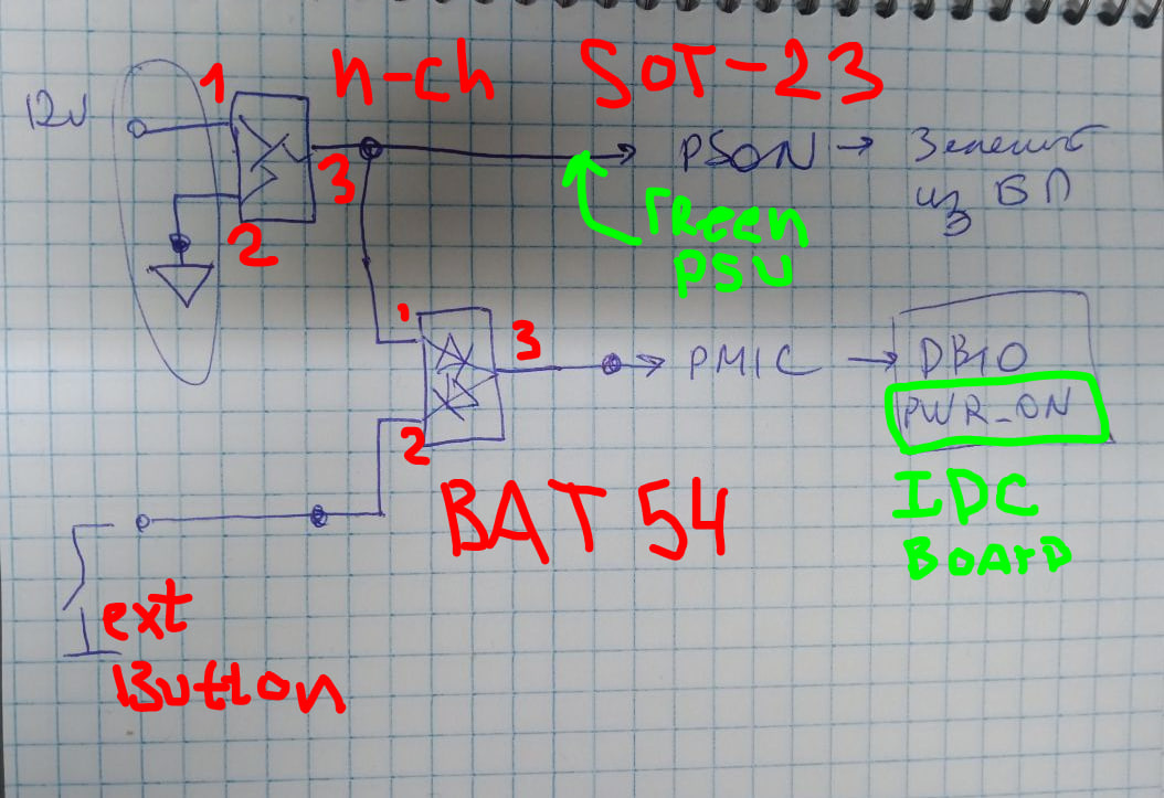
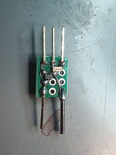
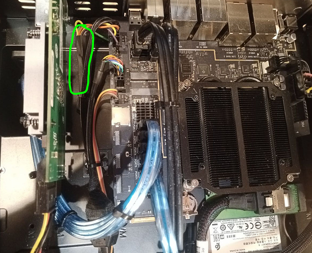
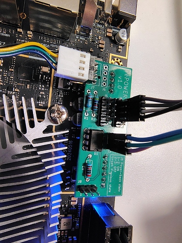
Hi, it seems I have the same one, but based on regular N-ch FET, for example, BSS138P and BAT54
Also, I use small PCB with these semi and place it in heat shrink tube. Works well.
I like your approach; simple and effective. Where are you getting the 12V control signal from?
Hi
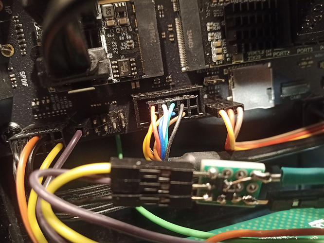
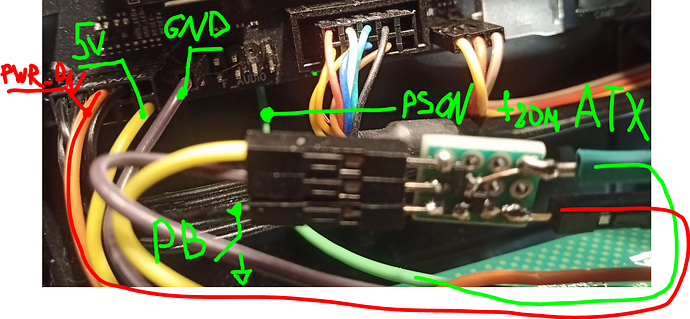
I use this schem for different cases, so it can be not only 12V from ATX, for example, but also 5V directly from the board. In the photo above you can see yellow wire connected to pin 9 of the F_PANEL IDC connector. This pin is VCC5V0_SYS power rail:
Also, I use pin 2 of the Audio connector as GND. The green wire is PS_ON that was pull out from ATX connector.
