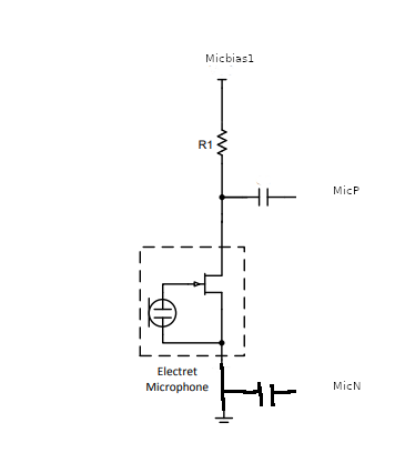
I am going to start with electrets and try and reopen the conv incase I have missed good info from before or anyone has missed how to use analogue Mics.

Apols about my drawing but thats the circuit from what I can gather from Rockchip and generally how electrets are wired.
R1 approx 2k2 (I used 4k7 because couldn’t find 2k2)
The to DC blocking caps are 100nf.
That is a single ended mic circuit and the dc blocker on GND doesn’t make much sense in that its gnd and prob not needed but hey.
Here is the bit where I record myself of a wired electret like the above.
https://drive.google.com/file/d/1ZAenQC1tOORApfbuPcxRB8Cr8zCgVSlc/view?usp=sharing
Its not all bad as the electret modules you can get are far better than that, but I just wanted to ask is that the results you get?
PS amixer -c1 cset numid=51 1 sets micbias1 and dunno what ADC Main MicBias is in alsamixer and why you seem to be able to have one off and one on and then swap the other way with one off and one on it makes no difference but seems to sound worse than both on.
My db gain is 24db on that mic and the HPF cutoff is on but I don’t think that does a thing.
So interested in what you guys got you got better results? Tell me how 
Also I should mention that the mic gain for mic input does not seem to be set.
ACODEC_ADC_ANA_CON1
Address: Operational Base + offset (0x0344)
Bit Attr Reset Value Description
31:6 RO 0x0 reserved
5:4 RW 0x0
ADC_CH2_MIC_GAIN
The gain signal of MIC module in the ADC channel 2.
2’b00: 0dB
2’b11: 20dB
Others: reserve
Note: When ADC is used as loopback, it is recommended to
configure 2’b00. When ADC is used as MIC input, it is
recommended to configure 2’b11.
3:2 RO 0x0 reserved
1:0 RW 0x0
ADC_CH1_MIC_GAIN
The gain signal of MIC module in the ADC channel 1.
2’b00: 0dB
2’b11: 20dB
Others: reserve
Note: When ADC is used as loopback, it is recommended to
configure 2’b00. When ADC is used as MIC input, it is
recommended to configure 2’b11.
If you check that register is likely 2'b00: 0dB still trying to figure out what is meant as ADC is used as loopback?
The buzz is awful really…
If you want to change registers the io tool in the testing repo can be downloaded with
wget https://github.com/radxa/apt/raw/gh-pages/buster-testing/pool/main/i/io/io_0.1_arm64.deb
sudo dpkg -i io_0.1_arm64.deb
If you look at the address mapping ff560000 Audio Codec PHY then add the offset to that base address.
As in sudo io 0xff560344 0x33 for the above.
The other weird thing is without micbias1 enabled or adcmainbias you can still record a very tiny signal but there definately is voltage as when normalised in audacity I can hear myself with clarity.
The noise is also there and where it comes form I don’t know.
PS eventually I did find a 2k2 resistor but made no difference.