Yeah, as a desktop its indeed something else.
and i want to use it as desktop with that case and maybe i will solv this problem by soldering some wires to the button and gluing another button on the case
If it is possible to use a button that is connected to the GPIO and start it that way, i would rather advise that to use. Why? I dont have the trust in that button to work for years on the board, day in day out being pressed.
I have two rock 5B, but both of them i will not press that button that often. One would be my low-power 24/7 server and the other, i am playing to have retropi/KODI running on it. The second one will be turned off through cli and turned on when i press the power strip to turn on (use a power strip with a button to prevent standy power consumption while i am asleep)
Well now i think about it. You could do the same i guess. Right? Just turn it off and turn it on using a power strip right?
the powerstrip methode is not elegant i would rather replace the button after arround a year but i also have pretty good microsoldering skills so for me the replacing would only take me arround 10 minutes (including searching for a similar button in my pcb collection)
That indeed is also possible. The down and dirty way for the rednecks among is :). I would have just fixed the powerstrip underneath table.
both solutions are good solutions but the more elegant for me is definitly using the internal button
1 Like
Anyone has a good hint on how to open the case after fitting in all in ? Mine’s stuck ![]()
1 Like
I know. Its a BIG hassle. I dont even know how i opened my first case. Later on, i saw that one of those plastic thingys that would fit in the iron rectangle holes has become white. In other words it apparently have been bend.
Very solid and good case, but made like those Ikea furniture. Put them together and DO NOT take them apart in the future XD.
It took quite a bit of prying - removed the screws and pry out one of the small green plastics outwards..
I’ve removed the green tab to make it easier to remove that panel. Whole case still fits very nicely..
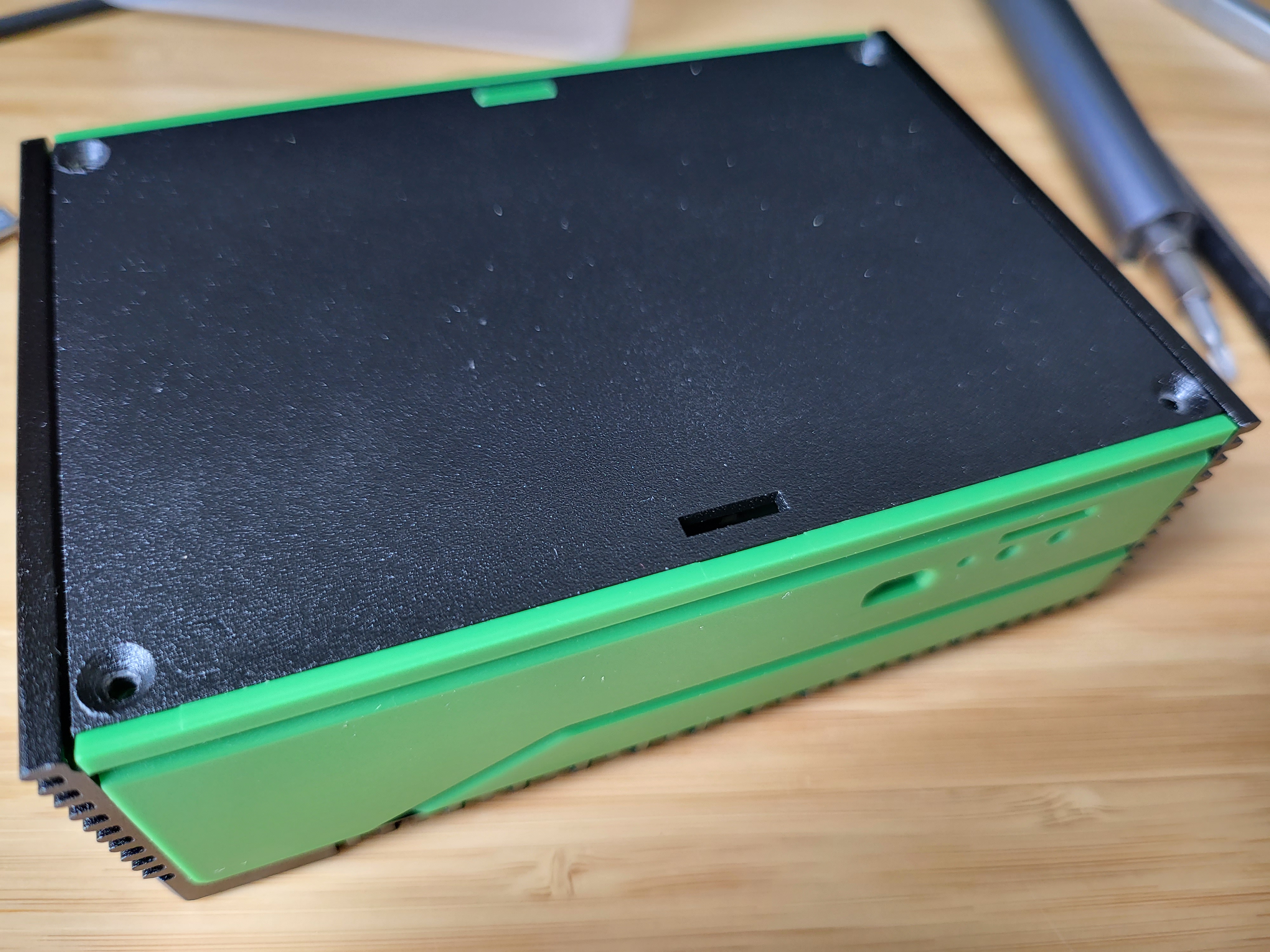
It sure looks pretty, as long as you aren’t averse to green, but there are a few issues:
- The heads of the countersunk screws supplied for mounting the board to the base of the case foul the board mounts on the sides of the case, so that the base has to be forced in.
- No slots for CSI/DSI cables … Dremel ahoy!
- Not enough room for a NVME heatsink.
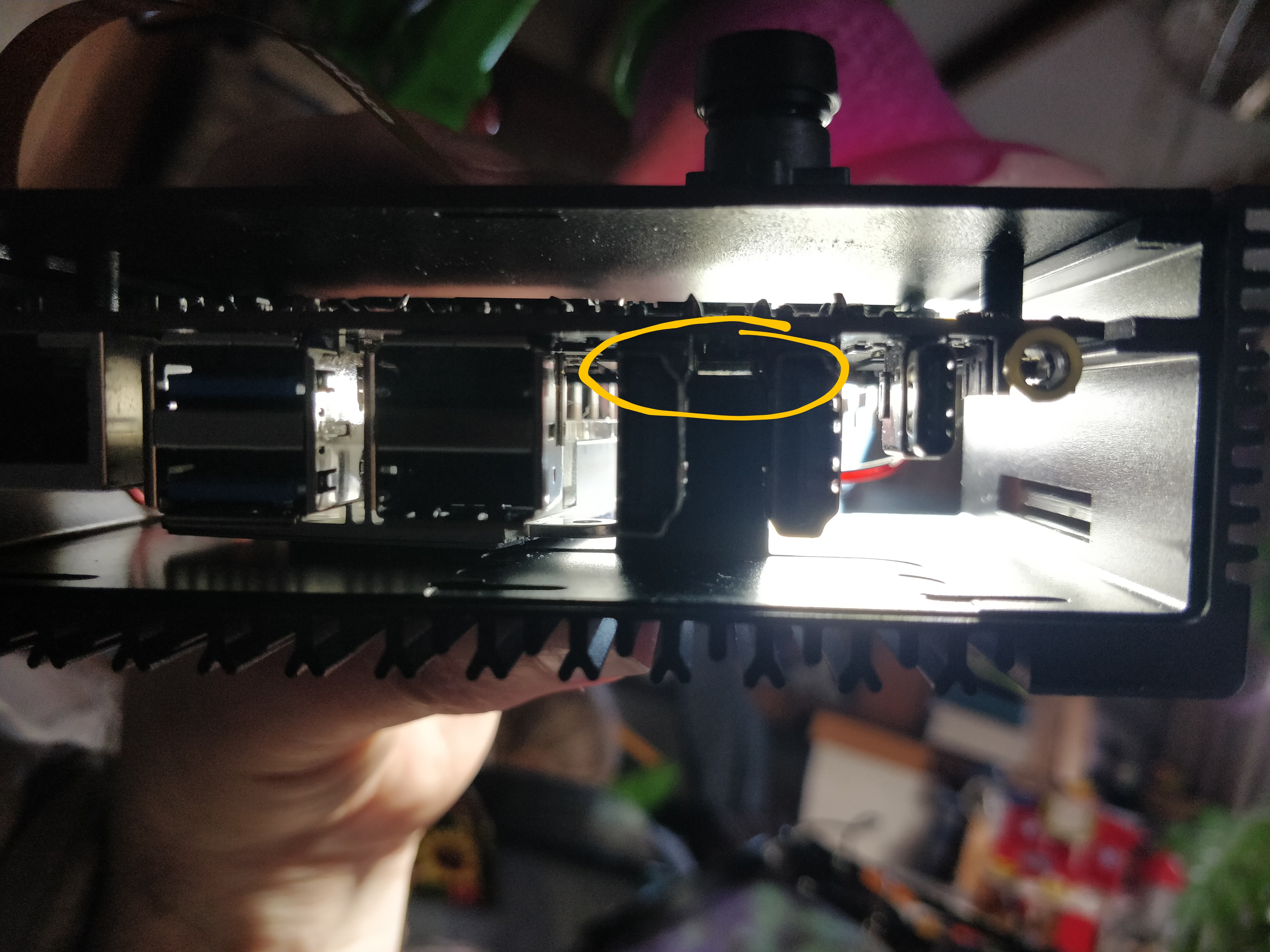
- The block that APPEARS to be for conducting heat away from the SOC doesn’t actually touch the SOC … I would guess about 0.5mm gap … hard to tell from the photo. Small pouch of paste supplied … perhaps there’d be enough to fill the gap, maybe … but what a poor solution.
- There are no holes/slots in the base to suit wall mounting … made more difficult by the way the case screws together.
I could cut away the block and install the fan, or even keep they block and use a copper shim, and I guess I could grind down a NVME heatsink at the right angle for it to press against the bottom plate (the drive sits at an angle, so the socket end is about 1mm closer to the plate) … but really?
I had expected a better design given the previous cases from Radxa.
2 Likes
For NVMe a 2mm thermal pad works.
That the block doesn’t touch the SOC is worrisome. I guess I’m getting another 0.5mm thermal pad there.
And the whole “force the base in” thing, yikes.
Haven’t gotten mine from Ameridroid yet. Patience … patience.
I ordered a 3mm hope that also fits and used thermal paste for the SOC.
Hmm, perhaps this case mod is in my future. Putting it together the first time was quite difficult, I am loathing the next time i need to take it apart!
Got my metal case today, isy=talled the SoC into the case.
NVMe and eMMC fit perfectly.
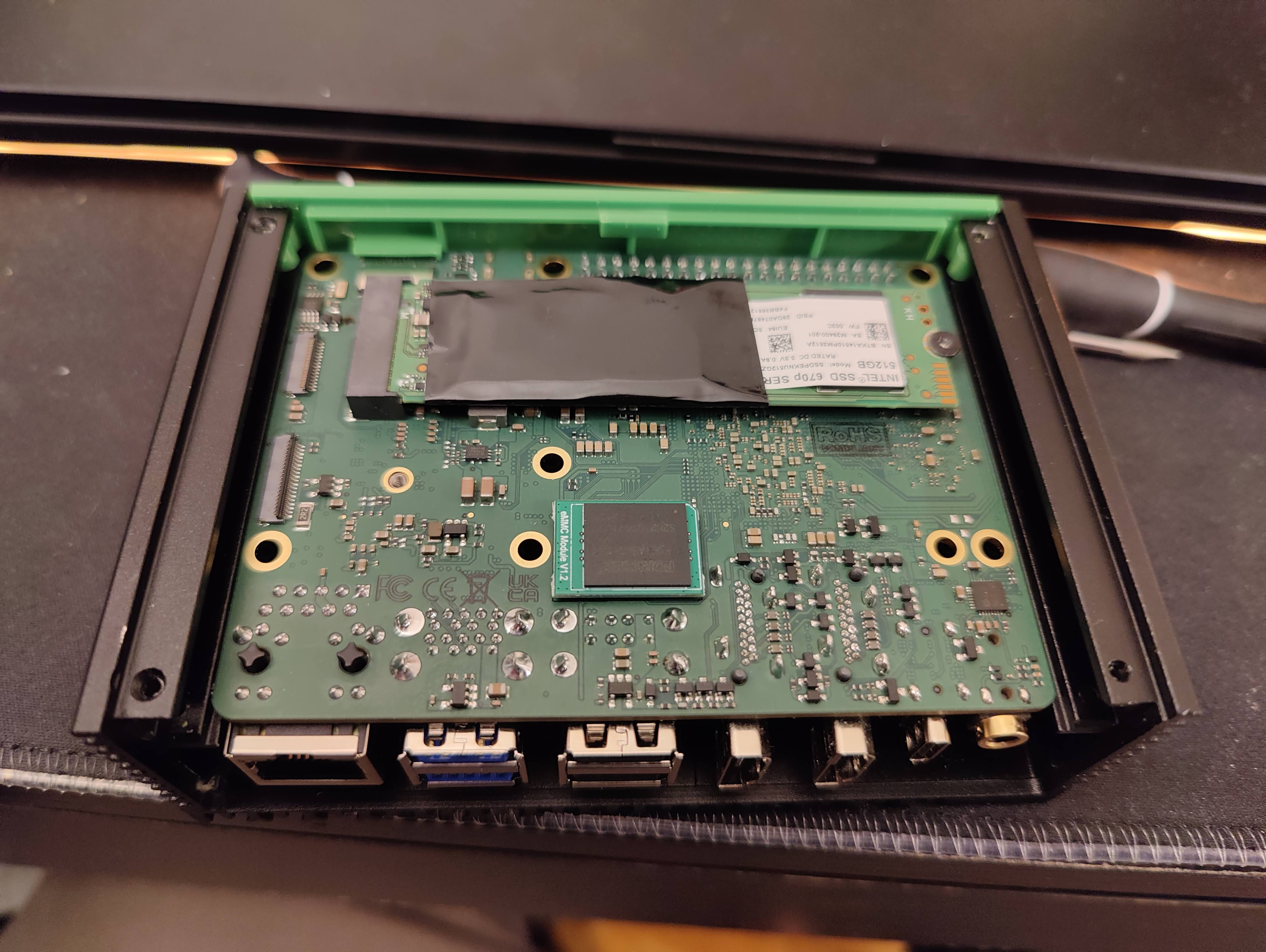
Also I’ve applied some thermal paste:
With thermal paste the CPU idle temp reduced from ~43°C to ~36-37°C in the same environment.
alex@rock-5b:~$ sensors
gpu_thermal-virtual-0
Adapter: Virtual device
temp1:        +36.1 C

littlecore_thermal-virtual-0
Adapter: Virtual device
temp1:        +37.0 C

bigcore0_thermal-virtual-0
Adapter: Virtual device
temp1:        +36.1 C

tcpm_source_psy_4_0022-i2c-4-22
Adapter: rk3x-i2c
in0:          12.00 V  (min = +12.00 V, max = +12.00 V)
curr1:         2.25 A  (max =  +2.25 A)

npu_thermal-virtual-0
Adapter: Virtual device
temp1:        +36.1 C

center_thermal-virtual-0
Adapter: Virtual device
temp1:        +36.1 C

bigcore1_thermal-virtual-0
Adapter: Virtual device
temp1:        +37.0 C

soc_thermal-virtual-0
Adapter: Virtual device
temp1:        +36.1 C  (crit = +115.0 C)
As for me, the main minus is a hidden GPIO including UART pins.
UPD:
The average temperature under 100% CPUs load (Building the kernel):
Every 2.0s: sensors                                                                                                                                                              rock-5b: Sun Dec  4 07:55:24 2022

gpu_thermal-virtual-0
Adapter: Virtual device
temp1:        +51.8 C

littlecore_thermal-virtual-0
Adapter: Virtual device
temp1:        +56.4 C

bigcore0_thermal-virtual-0
Adapter: Virtual device
temp1:        +58.2 C

tcpm_source_psy_4_0022-i2c-4-22
Adapter: rk3x-i2c
in0:          12.00 V  (min = +12.00 V, max = +12.00 V)
curr1:         2.25 A  (max =  +2.25 A)

npu_thermal-virtual-0
Adapter: Virtual device
temp1:        +53.6 C

center_thermal-virtual-0
Adapter: Virtual device
temp1:        +52.7 C

bigcore1_thermal-virtual-0
Adapter: Virtual device
temp1:        +58.2 C

soc_thermal-virtual-0
Adapter: Virtual device
temp1:        +56.4 C  (crit = +115.0 C)
What size/type of screw do i use to attach the rock 5b to the metal cases backplate?
Or did you all get the needed screws included with the metal case? Mine didn’t include any. Just the 4 tiny ones that hold the case and backplate together.
They came in a small bag with the case … in fact there were 5 in mine!
They’re M3 … I’d guess at 6-8mm length (from memory)
It must be really hit or miss on the mounting screws-I didn’t get any either-luckily I have a couple of bags of screws and other mounting hardware from years of computer building so I’ll find something!
1 Like
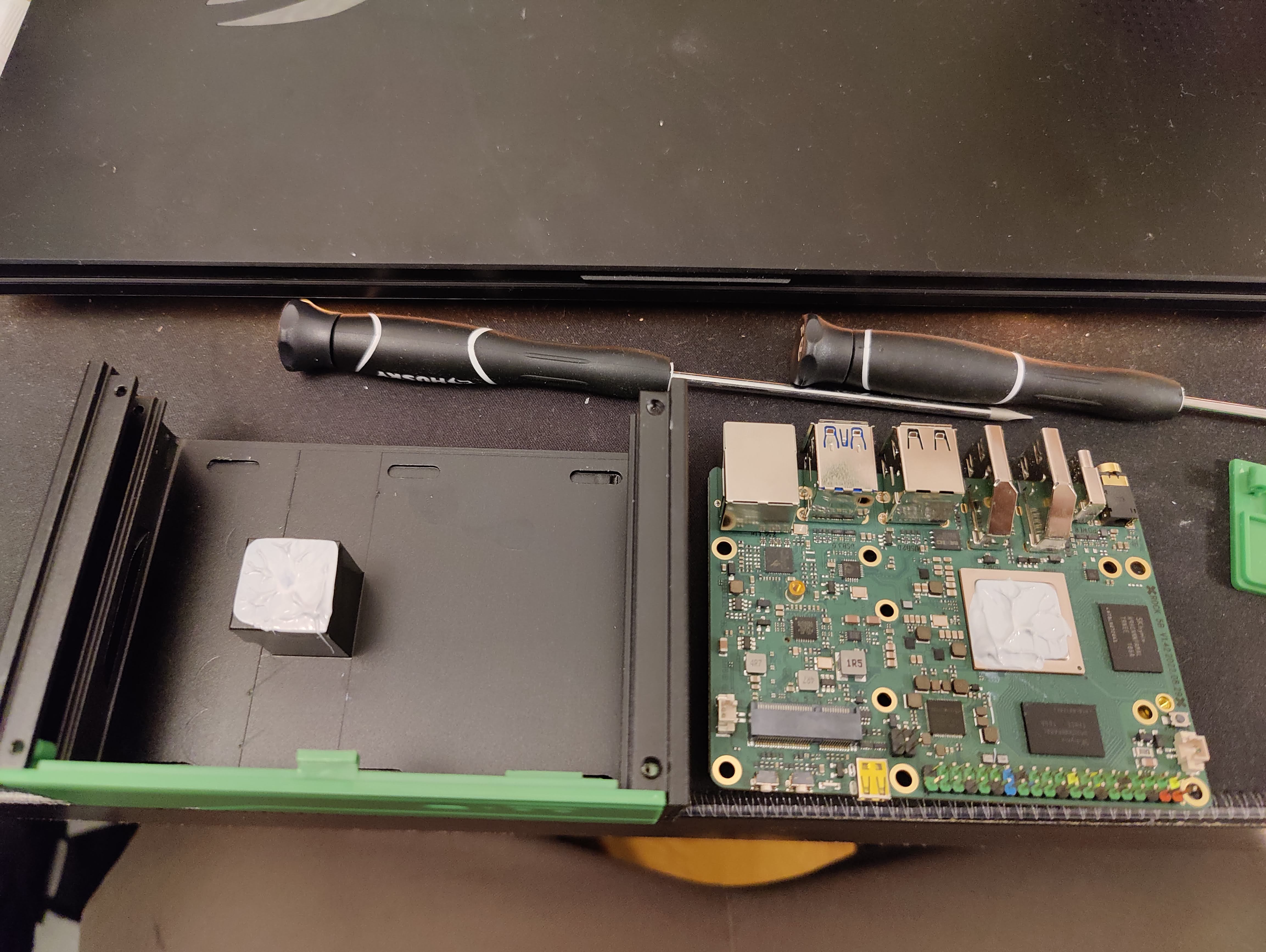
The idea of using goop to fill the gap between the case-post and the SOC didn’t sit well with me, so I’ve completely solved the issue by using 20mm x 20mm x 0.3mm Copper Shims
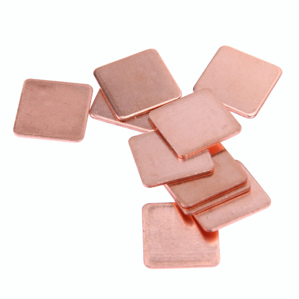
(clearly ^^ these are NOT 0.3mm!)
I actually bought 0.3mm and 0.5mm, but the 0.3mm lot arrived first!
I used two shims, and a thin smear of the (recycled) heatsink paste on each surface.
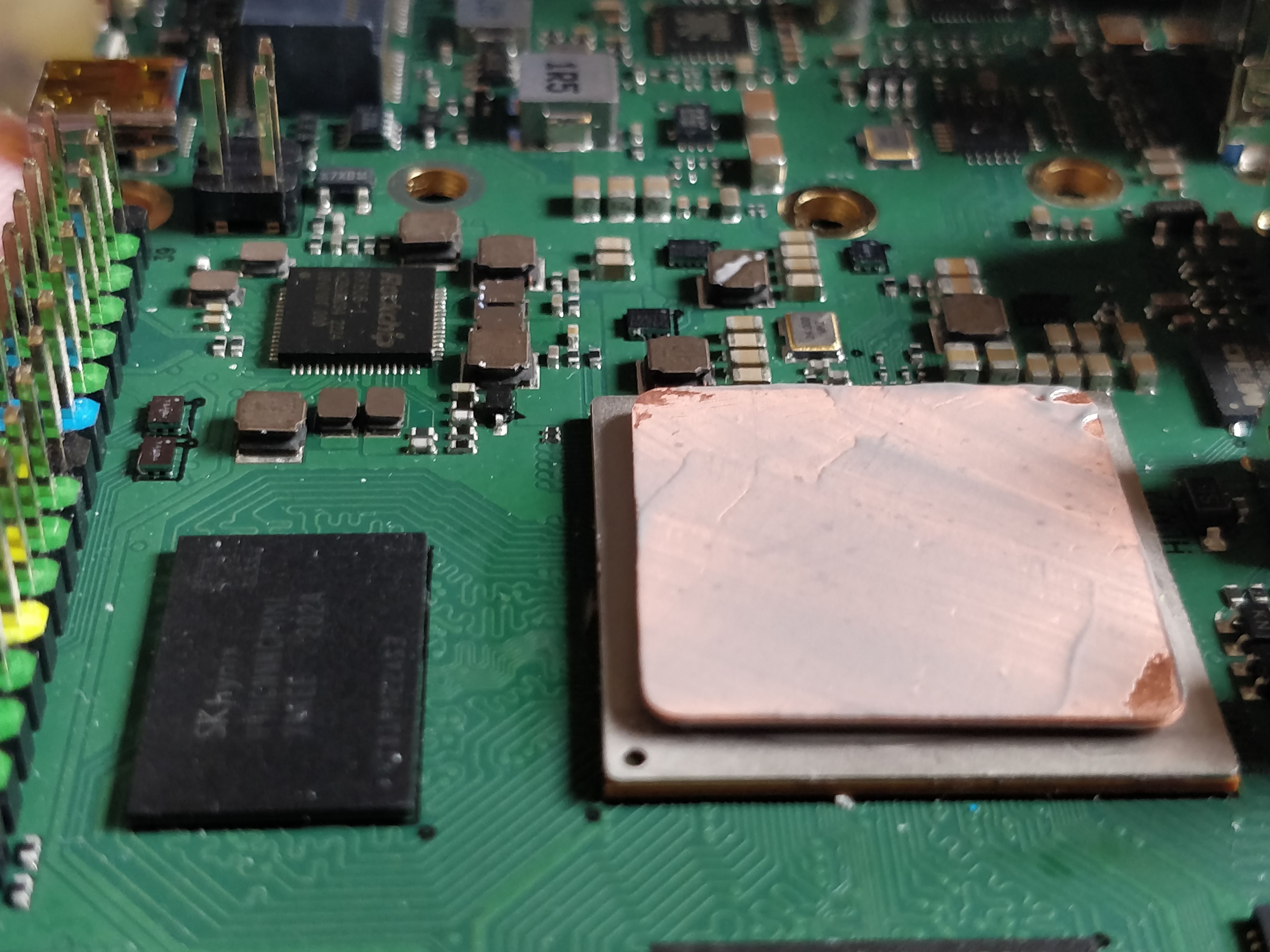
I did actually get the shims more central than this, it’s just that I took a photo while testing how tight the fit was … case reassembled WITH the cooling fan stuck upside-down to the inside of the case (for now) ;).
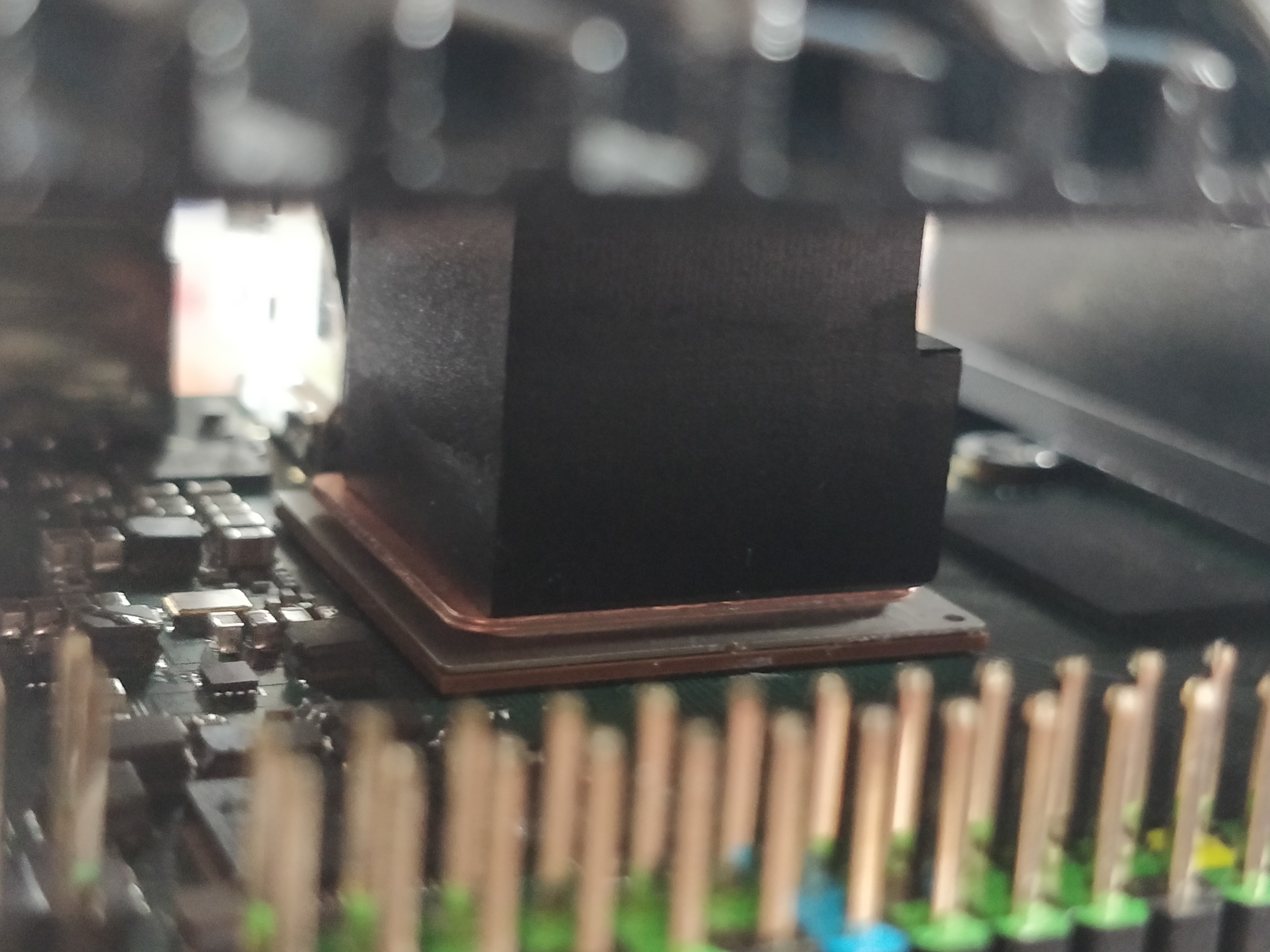
Case + fan + Rock5B now operate as I would expect, and certainly a HUGE improvement on what it was. Previously I had the fan minimum set to 45C in order to have a “mostly silent” experience, but that’s now reduced to 40C, with ‘idle’ temps at 35C (idle-ish running a whole heap of docker stacks ![]() ). So now I’ve got the silence of a passive case, and the reassurance of (some+adjustable) active cooling under serious loads, even with a less-than-ideal position for the fan.
). So now I’ve got the silence of a passive case, and the reassurance of (some+adjustable) active cooling under serious loads, even with a less-than-ideal position for the fan.
No, I didn’t remove the anodising on the case-post, and I probably could have smoothed+polished the shims to prove a point, but extremely pleasing outcome regardless ![]() .
.
I have a more involved solution planned for the NVME drive when the parts are available/assembled … happy to share if it works.
3 Likes
UPDATE:
After ~100 minutes of
stress -c 8
at an ambient 26°C the BigCore temp was 57.3°C (and the entire case, of course!).
Previous temps with only the fan (I mean, the HSF) using the same test gave BigCore temp of 69.4°C (in the ‘acrylic’ case).
Once the stress test was cancelled, the BigCore temp reduced to 44.4°C in under 2 minutes, and the fan started turning off after ~5 minutes.
So, it seems to be a big reduction in SOC temp (assuming the whole case would NOT reach ~70°C over a significant period of time), but you end up with a big + hot brick under a sustained load ![]() . I probably should have run it overnight/all-day to ensure that the temp stabilised, but I ran out of time.
. I probably should have run it overnight/all-day to ensure that the temp stabilised, but I ran out of time.
1 Like
I actually bought 0.3mm and 0.5mm, but the 0.3mm lot arrived first!
I used two shims, and a thin smear of the (recycled) heatsink paste on each surface.
I would say if you can manage to have only one shim instead of 2 would be better, as you might loose a bit of conductivity between each layer.
Would the 0.5mm shim alone with thermal paste on both faces be enough ?
Wonder what is best between this solution and just a thermal pad