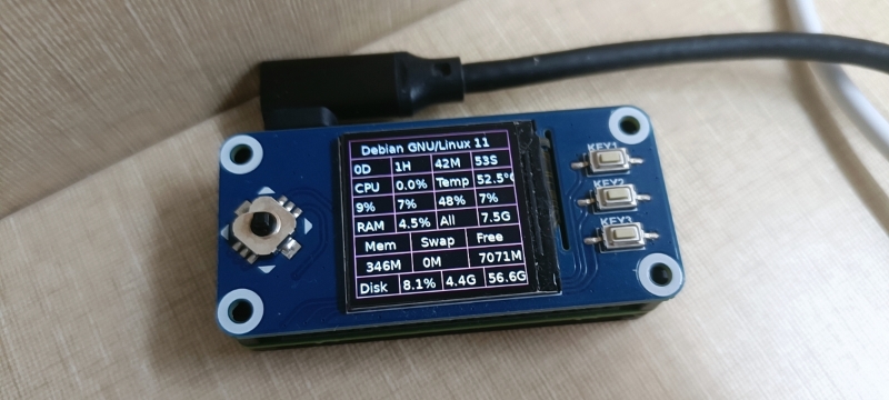
I purchased a Waveshare 1.3inch LCD HAT. Its Wiki is https://www.waveshare.com/wiki/1.3inch_LCD_HAT. I wrote a Python program for the 1.3inch_LCD_HAT on a Raspberry Pi Zero 2W. Now, I want to run it on a Radxa ZERO 3W. What modifications do I need to make? Since my development and testing have always been based on Raspberry OS, I’m not sure how to replicate it on RadxaOS. For example, enabling the SPI interface and the differences in GPIO.
I’m a newbie developer and this is my first time working with hardware development. I apologize for any inconvenience caused and hope to receive assistance.
1.3inch LCD HAT - Waveshare for Radxa ZERO 3W
you need to know the display ic and touch ic, and write a dts file to enable it
I tried writing Overlays and enabled it in rsetup.
/dts-v1/;
/plugin/;

#include <dt-bindings/gpio/gpio.h>
#include <dt-bindings/pinctrl/rockchip.h>
#include <dt-bindings/interrupt-controller/irq.h>

/ {
	metadata {
		title = "Waveshare 1.3inch LCD HAT";
		compatible = "radxa,zero3";
		category = "misc";
		exclusive = "GPIO4_C6", "GPIO4_C2", "GPIO4_C3", "GPIO3_C1", "GPIO3_B2", "GPIO3_A2";
		description = "Waveshare 1.3inch LCD HAT For Radxa Zero 3W.";
	};

	fragment@0 {
		target = <&spi3>;

		__overlay__ {
			status = "okay";
			#address-cells = <1>;
			#size-cells = <0>;
			pinctrl-names = "default", "high_speed";
			pinctrl-0 = <&spi3m1_cs0 &spi3m1_pins>;
			pinctrl-1 = <&spi3m1_cs0 &spi3m1_pins_hs>;

			st7789v@0 {
				compatible = "sitronix,st7789v";
				reg = <0>;
				spi-max-frequency = <40000000>;
                width = <240>;
                height = <240>;
                buswidth = <8>;
                regwidth = <8>;
                fps = <60>;
                rotate = <0>;
				debug = <0>;

				// configure pin assigment below
				dc-gpios = <&gpio3 RK_PC1 GPIO_ACTIVE_HIGH>;
				reset-gpios = <&gpio3 RK_PA2 GPIO_ACTIVE_LOW>;
			};
		};
	};
};
But it doesn’t seem to work. I still haven’t been able to light it up.
Could you please answer this question or provide relevant examples? I would be extremely grateful.
I’ve been trying to find a solution but haven’t succeeded in testing it yet. Could you please provide me with some overlays examples and a related Python demo? I would really appreciate your help.
Thank you very much, I tweaked my original overlays.
Below:
/dts-v1/;
/plugin/;

#include <dt-bindings/gpio/gpio.h>
#include <dt-bindings/pinctrl/rockchip.h>
#include <dt-bindings/interrupt-controller/irq.h>

/ {
	metadata {
		title = "Waveshare 1.3inch LCD HAT";
		compatible = "radxa,zero3";
		category = "misc";
		description = "Waveshare 1.3inch LCD HAT For Radxa Zero 3W.";
	};
};

&spi3{
	status = "okay";
	pinctrl-names = "default", "high_speed";
	pinctrl-0 = <&spi3m1_cs0 &spi3m1_pins>;
	pinctrl-1 = <&spi3m1_cs0 &spi3m1_pins_hs>;

	st7789v@0 {
		compatible = "sitronix,st7789v";
		reg = <0>; //chip select 0:cs0  1:cs1
		spi-max-frequency = <10000000>;
		rotate = <0>; //横屏90度旋转
		fps = <30>; //帧率
		buswidth = <8>; //数据线宽
		regwidth = <8>; //寄存器数据线宽
		width = <240>;
		height = <240>;
		cs-gpio = <&gpio4 RK_PC6 GPIO_ACTIVE_HIGH>; //片选 GPIO4 C6
		dc-gpios = <&gpio3 RK_PC1 GPIO_ACTIVE_HIGH>; //DC脚 GPIO3 C1
		reset-gpios = <&gpio3 RK_PA2 GPIO_ACTIVE_LOW>; //rest脚 GPIO3 A2
		debug = <0>;
    };
};
Now when I enabled it in rsetup and rebooted the device. I noticed that the screen lights up, and after the device boots, it shows the partially loaded content of the terminal before going off again and the ssh service resumes connecting.
I would like to know how to invoke it. Is there a relevant python example? Your answer is much appreciated.
does the screen showing ?
For python demo, may be you can refer to https://github.com/pimoroni/st7789-python.
Thank you very much for your help. I have found my problem and have tested it. The overlay and related code is being refined.
This is the display part of the screen overlay.
/dts-v1/;    // Device Tree Specification version 1
/plugin/;     // Plugin mechanism for Device Tree overlays

#include <dt-bindings/gpio/gpio.h>
#include <dt-bindings/pinctrl/rockchip.h>
#include <dt-bindings/interrupt-controller/irq.h>

/ {           // Root node of the Device Tree
    metadata {    // Metadata node containing general information about the overlay
        title = "Waveshare 1.3inch LCD HAT Display"; // Title of the overlay
        compatible = "radxa,zero3"; // Compatible with Radxa Zero 3
        category = "misc"; // Category of the overlay
        description = "Waveshare 1.3inch LCD HAT For Radxa Zero 3W. This is the display part of the screen overlay."; // Detailed description of the overlay
    };
};

&spi3 { // Reference to the spi3 node, which represents SPI bus 3
    status = "okay"; // Set the status to okay to enable the SPI bus

    pinctrl-names = "default", "high_speed"; // Define pin control states: default and high_speed
    pinctrl-0 = <&spi3m1_cs0 &spi3m1_pins>; // Pin configuration for default state
    pinctrl-1 = <&spi3m1_cs0 &spi3m1_pins_hs>; // Pin configuration for high_speed state

    st7789v@0 { // Node defining the ST7789V LCD display connected to SPI bus 3, chip select 0
        compatible = "sitronix,st7789v"; // Compatible with ST7789V display driver
        reg = <0>; // Chip select 0 (cs0)
        spi-max-frequency = <10000000>; // Maximum SPI frequency (10 MHz)
        rotate = <90>; // Rotation angle for the display (90 degrees)
        fps = <30>; // Frame rate (30 frames per second)
        buswidth = <8>; // Data bus width (8 bits)
        regwidth = <8>; // Register data bus width (8 bits)
        width = <240>; // Display width in pixels
        height = <240>; // Display height in pixels
        cs-gpio = <&gpio4 RK_PC6 GPIO_ACTIVE_HIGH>; // Chip select GPIO: GPIO4 PC6, active high
        dc-gpios = <&gpio3 RK_PC1 GPIO_ACTIVE_HIGH>; // Data/Command GPIO: GPIO3 PC1, active high
        reset-gpios = <&gpio3 RK_PA2 GPIO_ACTIVE_LOW>; // Reset GPIO: GPIO3 PA2, active low
        debug = <0>; // Debug option (0 for disabled)
    };
};
This is the key part of the screen overlay.
/dts-v1/;    // Device Tree Specification version 1
/plugin/;     // Plugin mechanism for Device Tree overlays

/ {           // Root node of the Device Tree
    metadata {    // Metadata node containing general information about the overlay
        title = "Waveshare 1.3inch LCD HAT KEY"; // Title of the overlay
        compatible = "radxa,zero3"; // Compatible with Radxa Zero 3
        category = "misc"; // Category of the overlay
        description = "Waveshare 1.3inch LCD HAT For Radxa Zero 3W. This is the key part of the screen overlay"; // Detailed description of the overlay
    };
};

&{/} {    // Reference to the root node
    buttons_joystick { // Node defining buttons and joystick inputs
        compatible = "gpio-keys"; // Compatible with GPIO keys driver
        pinctrl-names = "default"; // Name of the pin control state
        pinctrl-0 = <&buttons_joystick_pins>; // Reference to the pin configuration

        key1 { // Key1 button
            label = "KEY1"; // Label for the button
            gpios = <&gpio3 5 1>; // GPIO configuration: &gpio3 is the GPIO controller, 5 is the pin number, 1 represents input mode
        };

        key2 { // Key2 button
            label = "KEY2";
            gpios = <&gpio3 6 1>;
        };

        key3 { // Key3 button
            label = "KEY3";
            gpios = <&gpio3 7 1>;
        };

        joy_up { // Joystick up direction
            label = "JOY_UP";
            gpios = <&gpio3 12 1>;
        };

        joy_down { // Joystick down direction
            label = "JOY_DOWN";
            gpios = <gpio&3 4 1>;
        };

        joy_left { // Joystick left direction
            label = "JOY_LEFT";
            gpios = <&gpio3 11 1>;
        };

        joy_right { // Joystick right direction
            label = "JOY_RIGHT";
            gpios = <&gpio1 4 1>;
        };

        joy_press { // Joystick press action
            label = "JOY_PRESS";
            gpios = <&gpio3 19 1>;
        };
    };
};

&pinctrl { // Reference to the pinctrl node
    buttons_joystick { // Pin control configuration for buttons and joystick
        buttons_joystick_pins: buttons-joystick-pins { // Pin configuration node
            rockchip,pins = // Rockchip-specific pin configuration
                <3 5 0 &pcfg_pull_up>, // GPIO3_IO5, function 0, pull-up configuration
                <3 6 0 &pcfg_pull_up>, // GPIO3_IO6, function 0, pull-up configuration
                <3 7 0 &pcfg_pull_up>, // GPIO3_IO7, function 0, pull-up configuration
                <3 12 0 &pcfg_pull_up>, // GPIO3_IO12, function 0, pull-up configuration
                <3 4 0 &pcfg_pull_up>, // GPIO3_IO4, function 0, pull-up configuration
                <3 11 0 &pcfg_pull_up>, // GPIO3_IO11, function 0, pull-up configuration
                <1 4 0 &pcfg_pull_up>, // GPIO1_IO4, function 0, pull-up configuration
                <3 19 0 &pcfg_pull_up>; // GPIO3_IO19, function 0, pull-up configuration
        };
    };
};
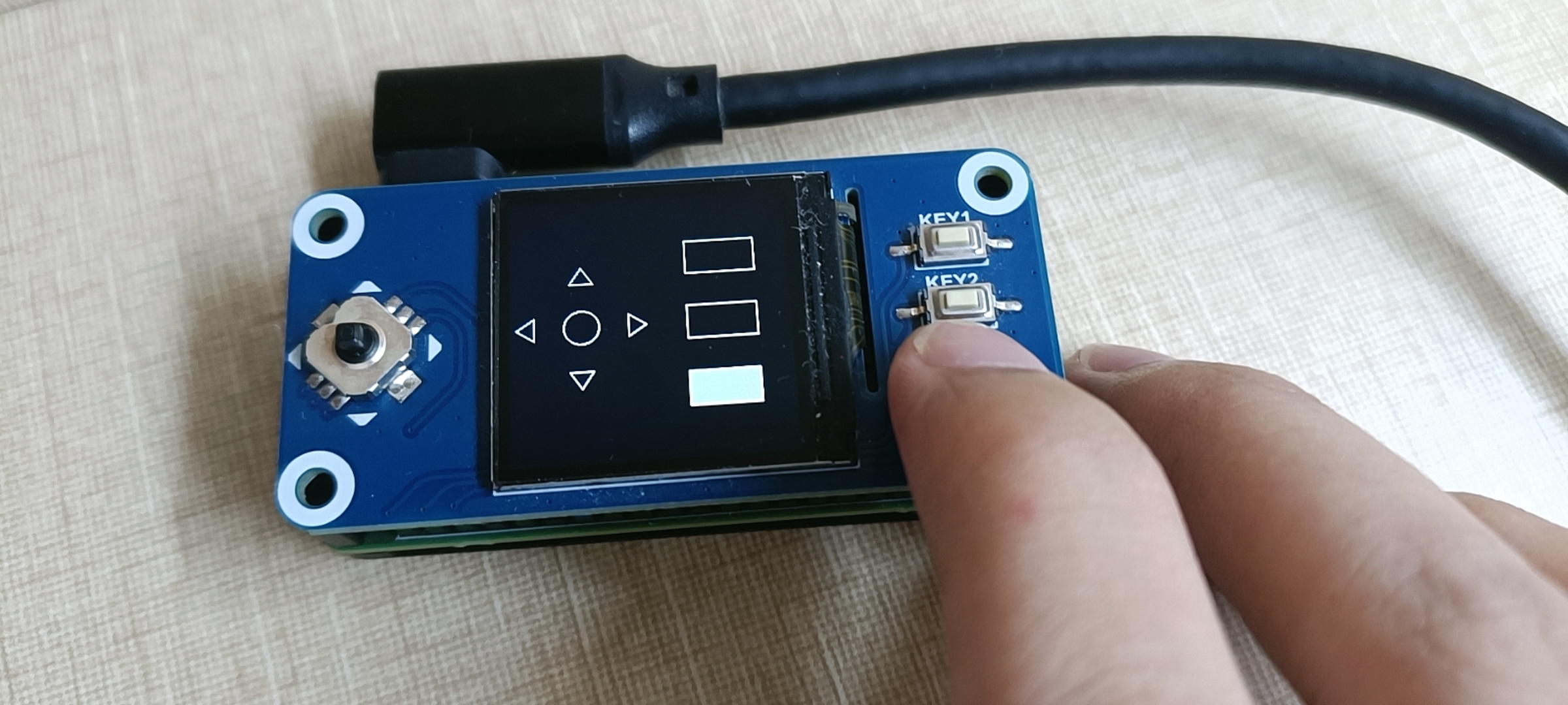
Here’s a case of Python code for screen testing.
import gpiod
import time
import signal
import sys
from PIL import Image, ImageDraw

# Button configuration: format is (chip name, pin number)
buttons = {
    "Left": ("gpiochip3", 11),     # GPIO3_B3
    "Up": ("gpiochip3", 12),       # GPIO3_B4
    "Press": ("gpiochip3", 19),   # GPIO3_C3
    "Down": ("gpiochip3", 4),    # GPIO3_A4
    "Right": ("gpiochip1", 4),    # GPIO1_A4
    "KEY3": ("gpiochip3", 7),     # GPIO3_A7
    "KEY2": ("gpiochip3", 6),     # GPIO3_A6
    "KEY1": ("gpiochip3", 5)      # GPIO3_A5
}

# Open GPIO chips and configure pins as input mode
chips = {}
lines = {}
prev_values = {}  # Store the previous state of each button

# Set screen size
WIDTH, HEIGHT = 240, 240

# Create an image and a drawing object
image = Image.new("RGB", (WIDTH, HEIGHT), "BLACK")  # Black background
draw = ImageDraw.Draw(image)

# Draw background
def draw_background():
    # Draw joystick (left side)
    center_x, center_y = WIDTH // 4, HEIGHT // 2
    pad_size = 80
    # Direction indicates triangle, fill with black
    draw.polygon([(center_x - 10, center_y - pad_size//2), (center_x, center_y - pad_size//2 - 15), (center_x + 10, center_y - pad_size//2)], outline=(255,255,255), fill="BLACK")  # Up
    draw.polygon([(center_x - pad_size//2, center_y - 10), (center_x - pad_size//2 - 15, center_y), (center_x - pad_size//2, center_y + 10)], outline=(255,255,255), fill="BLACK")  # Left
    draw.polygon([(center_x + pad_size//2, center_y - 10), (center_x + pad_size//2 + 15, center_y), (center_x + pad_size//2, center_y + 10)], outline=(255,255,255), fill="BLACK")  # Right
    draw.polygon([(center_x - 10, center_y + pad_size//2), (center_x, center_y + pad_size//2 + 15), (center_x + 10, center_y + pad_size//2)], outline=(255,255,255), fill="BLACK")  # Down
    draw.chord((center_x - 15, center_y - 15, center_x + 15, center_y + 15), 0, 360, outline=(255,255,255), fill="BLACK")  # Center button

    # Draw KEY buttons (right side), fill with black
    key_x = WIDTH * 3 // 4
    key_width, key_height = 60, 30
    key_y = [HEIGHT // 4 - key_height//2, HEIGHT//2 - key_height//2, HEIGHT*3//4 - key_height//2]
    for i in range(3):
        draw.rectangle((key_x - key_width//2, key_y[i], key_x + key_width//2, key_y[i] + key_height), outline=(255,255,255), fill="BLACK")

# Draw button state
def draw_button_state(name, pressed):
    # Button color (green means pressed)
    color = (0, 255, 0)  # Green
    center_x, center_y = WIDTH // 4, HEIGHT // 2
    pad_size = 80
    key_x = WIDTH * 3 // 4
    key_width, key_height = 60, 30
    key_y = [HEIGHT // 4 - key_height // 2, HEIGHT // 2 - key_height // 2, HEIGHT * 3 // 4 - key_height // 2]

    # Fill with green if button is pressed
    if pressed:
        if name == "Up":
            draw.polygon([(center_x - 10, center_y - pad_size//2), (center_x, center_y - pad_size//2 - 15), (center_x + 10, center_y - pad_size//2)], outline=(255,255,255), fill=color)
        elif name == "Left":
            draw.polygon([(center_x - pad_size//2, center_y - 10), (center_x - pad_size//2 - 15, center_y), (center_x - pad_size//2, center_y + 10)], outline=(255,255,255), fill=color)
        elif name == "Right":
            draw.polygon([(center_x + pad_size//2, center_y - 10), (center_x + pad_size//2 + 15, center_y), (center_x + pad_size//2, center_y + 10)], outline=(255,255,255), fill=color)
        elif name == "Down":
            draw.polygon([(center_x - 10, center_y + pad_size//2), (center_x, center_y + pad_size//2 + 15), (center_x + 10, center_y + pad_size//2)], outline=(255,255,255), fill=color)
        elif name == "Press":
            draw.chord((center_x - 15, center_y - 15, center_x + 15, center_y + 15), 0, 360, outline=(255,255,255), fill=color)
        elif name == "KEY1":
            draw.rectangle((key_x - key_width // 2, key_y[0], key_x + key_width // 2, key_y[0] + key_height), outline=(255,255,255), fill=color)
        elif name == "KEY2":
            draw.rectangle((key_x - key_width // 2, key_y[1], key_x + key_width // 2, key_y[1] + key_height), outline=(255,255,255), fill=color)
        elif name == "KEY3":
            draw.rectangle((key_x - key_width // 2, key_y[2], key_x + key_width // 2, key_y[2] + key_height), outline=(255,255,255), fill=color)

# Convert image to RGB565 format and ensure correct byte order
def rgb_to_rgb565(image):
    result = bytearray()
    for pixel in image.getdata():
        r, g, b = pixel[:3]
        red = (r >> 3) & 0x1F
        green = (g >> 2) & 0x3F
        blue = (b >> 3) & 0x1F
        rgb565 = (red << 11) | (green << 5) | blue
        result.append(rgb565 & 0xFF)
        result.append((rgb565 >> 8) & 0xFF)
    return result

def signal_handler(sig, frame):
    print("\nScript stopped")
    draw_background()
    byte_data = rgb_to_rgb565(image)
    with open("/dev/fb0", "wb") as fb:
        fb.write(byte_data)
    for chip in chips.values():
        chip.close()
    sys.exit(0)

# Register signal handler function
signal.signal(signal.SIGTSTP, signal_handler)

def detect_button_press():
    try:
        # Initially draw the background
        draw_background()
        # Get GPIO chip and pin
        for name, (chip_name, pin) in buttons.items():
            if chip_name not in chips:
                chips[chip_name] = gpiod.Chip(chip_name)
            line = chips[chip_name].get_line(pin)
            line.request(consumer='button_test', type=gpiod.LINE_REQ_DIR_IN, flags=gpiod.LINE_REQ_FLAG_BIAS_PULL_UP)
            lines[name] = line
            prev_values[name] = line.get_value()

        while True:
            # Redraw the background to clear all button states
            draw_background()
            # Detect the state of each button and draw
            for name, line in lines.items():
                current_value = line.get_value()
                if current_value != prev_values[name]:
                    if current_value == 0:  # Button is pressed
                        print(f"Button {name} is pressed")
                    else:  # Button is released
                        print(f"Button {name} is released")
                    prev_values[name] = current_value
                # Draw button based on current state
                draw_button_state(name, current_value == 0)
            # Convert image to RGB565 format and write to frame buffer device
            byte_data = rgb_to_rgb565(image)
            with open("/dev/fb0", "wb") as fb:
                fb.write(byte_data)
            time.sleep(0.1)

    except KeyboardInterrupt:
        print("\nTest ended")
        draw_background()  # Restore initial background
        byte_data = rgb_to_rgb565(image)
        with open("/dev/fb0", "wb") as fb:
            fb.write(byte_data)
        for chip in chips.values():
            chip.close()

if __name__ == "__main__":
    detect_button_press()
GitHub Backup: Pi/Radxa ZERO 3W/Overlay/Waveshare 1.3inch LCD HAT at main · lingyuanzhicheng/Pi
Thanks for your sharing!
And can you please take a pr for this dts to our overlay repo?