Using an enc28j60 on the zero

Thanks for the feedback @RadxaYuntian

  • How does one know to use &gic as interrupt-parent and not &gpio_intc ? Both are tagged as interrupt controller and it was my understanding that I’d pick the one that is closest (in the tree) to the device node I’m describing.
  • You mention interrupts 81 and 82. spicc1 actually uses 90 and since the value 90 is not anywhere within meson-g12a-gpio.h I am confused as to how interrupt lines map to GPIO pins? So even if I could put 91 in this case, I still don’t know which pin to connect the interrupt line to.
  • What do these numbers stand for and how does one learn which is which?
  • What would you be able to do/check if you had the hardware module?

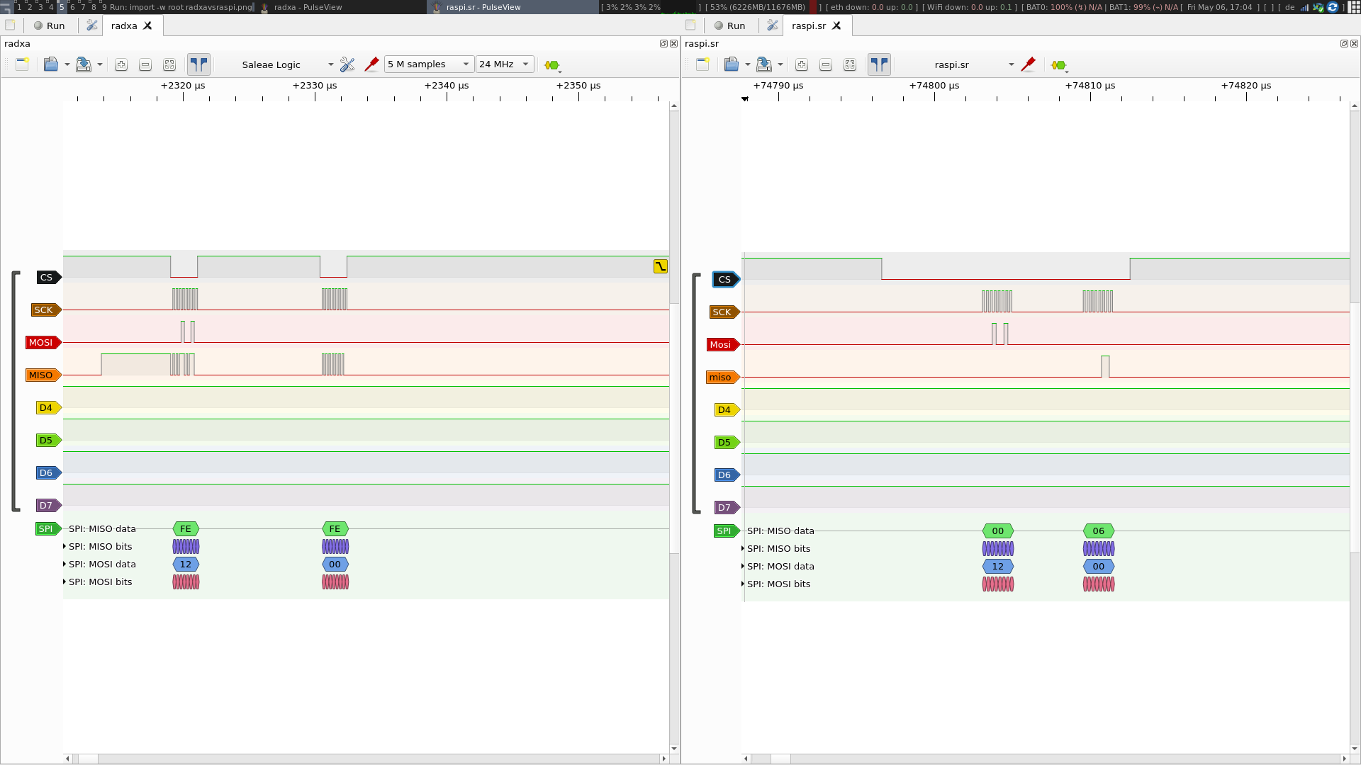
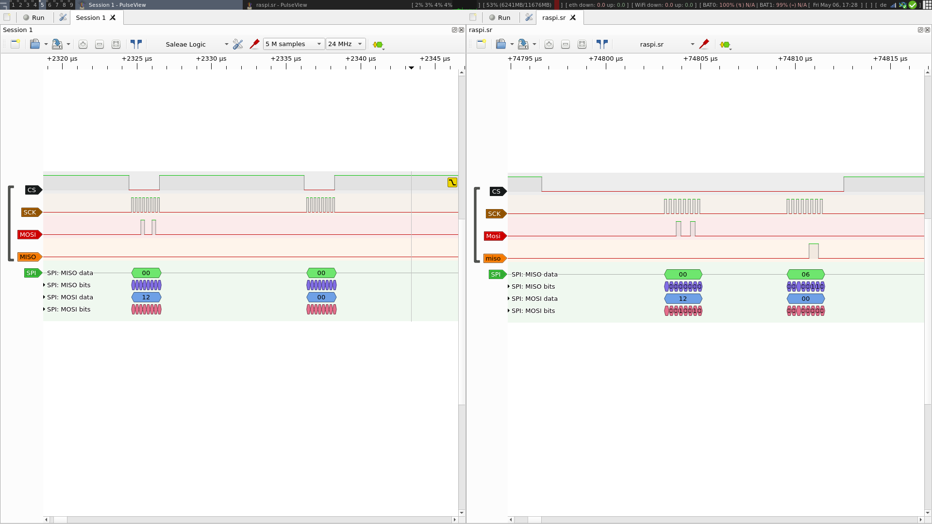
Without defining the interrupt-parent or interrupts, the results stay the same:

[    3.843415] enc28j60 spi1.0: Ethernet driver 1.02 loaded
[    3.849474] enc28j60 spi1.0: chip not found
[    3.849597] enc28j60: probe of spi1.0 failed with error -5

Maybe what isn’t entirely clear here is that the enc28j60 module has an interrupt pin and from what I read elsewhere, the module won’t work without this pin being connected.
So, the interrupt-line must IMHO map to a GPIO pin. I do not currently see how this is done.

My hypothesis is thus that the correct interrupt-parent is actually the gpio_intc and not gic directly.

gpio_intc: interrupt-controller@f080 {
	compatible = "amlogic,meson-g12a-gpio-intc",
				"amlogic,meson-gpio-intc";
	reg = <0x0 0xf080 0x0 0x10>;
	interrupt-controller;
	#interrupt-cells = <2>;
	amlogic,channel-interrupts = <64 65 66 67 68 69 70 71>;
};

If this hypothesis is correct, I still need to figure out how to map physical GPIO pins to register indices within gpio_intc.

For reference, the raspberry-pi dts has this:

fragment@2 {
        target = <&spi0>;
        __overlay__ {
                /* needed to avoid dtc warning */
                #address-cells = <1>;
                #size-cells = <0>;

                status = "okay";

                eth1: enc28j60@0{
                        compatible = "microchip,enc28j60";
                        reg = <0>; /* CE0 */
                        pinctrl-names = "default";
                        pinctrl-0 = <&eth1_pins>;
                        interrupt-parent = <&gpio>;
                        interrupts = <25 0x2>; /* falling edge */
                        spi-max-frequency = <12000000>;
                        status = "okay";
                };
        };
};

fragment@3 {
        target = <&gpio>;
        __overlay__ {
                eth1_pins: eth1_pins {
                        brcm,pins = <25>;
                        brcm,function = <0>; /* in */
                        brcm,pull = <0>; /* none */
                };
        };
};

I also don’t know exactly how, but the value 25 here refers to their GPIO25 which is pin 22.
The same value is used below in the definition of the pins as well as above when specifying interrupts.

After reading the code again I think you are right.

IRQ number is different from GPIO number, but I can’t figure out how those numbers are calculated so I just put an unused one there. For example spicc0 can be mapped to different pins but the IRQ number is the same 81.

@kwisatz @RadxaYuntian did you ever figure this out?

We also need to use enc28j60 with Radxa Zero so just wondered :slight_smile:

Hi @shawaj,

In a nutshell: No

But let me post a quick summary of what is new since my last update. You can go from there and together we might get to a solution quicker.

I’ll split this in two:

  1. SPI communication
  2. The IRQ pin and pinmuxing/pinctrl

SPI communication

We spent over 6 hours on this using an oscilloscope to analyse what is happening on the wires between the radxa zero and the module, but also between the module and a raspberry pi where this works flawlessly.
The first thing I have to say is that the signals from the radxa zero are very noisy. It’s a little better using a power connector to USB-C rather than feeding it from a notebook, but it’s still very noisy. Especially looking at the clock signal, it looks more like a mountain range than a skyline.

The first thing we did was to reduce the SPI frequency. Although we can see a max-spi-frequency value of 12000000 being used for the raspberry pi and other SoCs, this will not work with the radxa. Setting it to 10000000 or lower was necessary to make any communication with the module work.

The initial problem we encountered was that the module never responded to anything from the radxa. What the enc28j60 driver does, is to poll the module’s revision ID via the SPI bus. If there is no answer, then we get chip not found as seen above. Reading the specs of the enc28j60 chip, we tried several things and what finally led to us getting the driver to recognize the module was to add a pull-up on the MISO connection.

Now, this may also be possible using a pinctrl section, specifying that the pin in question (here pin 21) needs a pull-up. In our case, we did it using a 1 kOhm resistor on the MISO connection. But since knowing how to define pinctrl in general is a problem with the meson chip (e.g. I wouldn’t know by which value to refer to it in the dts), we have not yet attempted to do this.

The IRQ pin

Using guesswork and this commit from Xingyu Chen on the LKML we finally came up with the following configuration for the interrupt pin:

interrupt-parent = <&gpio_intc>;
interrupts = <85 IRQ_TYPE_EDGE_FALLING>;

Here, the value 85 is derived from the following statement from that commit:

The Meson-G12A SoC uses the same GPIO interrupt controller IP block as the
other Meson SoCs, A totle of 100 pins can be spied on, which is the sum of:

  • 223:100 undefined (no interrupt)
    […]
  • 96:77 20 pins on bank GPIOX
    […]

and thus 77 + 8 (GPIOX_8) = 85

Having this, we can at least see some interrupts in cat /proc/interrupts for the driver by applying external stimulus to the pin (but not from the module itself it would appear).

 38:          0          0          0          0  meson-gpio-irqchip  85 Edge      enc28j60

Note that the interrupt pin is not required for the driver to detect the chip, but it is required in order to get an operational interface.

Where we’re currently stuck is getting the interface up. There are two symptoms that we can see (other than the interface simply not getting an IP address from e.g. a DHCP server):

  1. The devicetree code is still complaining about an invalid map for state default: enc28j60 spi1.0: there is not valid maps for state default
  2. The interface is and stays in state link down, no matter what.
[    3.867504] enc28j60 spi1.0: there is not valid maps for state default
[    3.869939] enc28j60 spi1.0: Ethernet driver 1.02 loaded
[    6.248128] enc28j60 spi1.0 eth0: link down
[    6.248819] enc28j60 spi1.0 eth0: multicast mode
[    6.257138] enc28j60 spi1.0 eth0: multicast mode

As for the invalid map, the pinctrl configuration that I have is still the following:

&periphs_pinctrl {
	enc28j60_int_pin: enc28j60_int_pin@0 {
		amlogic,pins = <85>;	/* or is it <&gpio 85> ? */
		amlogic,function = "irq"; /* in - whether "out" (1) or "in" (0) */
		// amlogic,function = <0>; /* in - whether "out" (1) or "in" (0) */
		amlogic,pull = <IRQ_TYPE_NONE>;
	};
};

As you can see, I experimented with using "irq" as the function and providing one or two cells for pins since I’ve seen similar things being done. However, neither combination results in a working network interface. And I have found no information (and no examples of other SPI peripherals being used with the meson g12a) that would specify how many cells are expected here.

Another person had a similar issue on the tegra/jetson platform using the same chip. They have added debugging information to the driver to get more insight into what is failing and that might be what we’re going to try next.

Others with a similar experience/problem:

I was able to get some more information from the driver by raising its debug level. But the output (0xfe) leads me to believe that what we’re seeing is not actually the module but simply the effect of the pull-up on the MISO connection:

[ 3221.882849] enc28j60 spi1.0: there is not valid maps for state default
[ 3221.883836] enc28j60 spi1.0: Ethernet driver 1.02 loaded
[ 3221.889042] enc28j60 spi1.0: enc28j60_hw_init() - HalfDuplex
[ 3221.891781] enc28j60 spi1.0: chip RevID: 0xfe
[ 3221.896839] enc28j60 spi1.0:  Hw initialized.
               HwRevID: 0xfe
               Cntrl: ECON1 ECON2 ESTAT  EIR  EIE
                      0xfe  0xfe  0xfe  0xfe  0xfe
               MAC  : MACON1 MACON3 MACON4
                      0x00   0x00   0x00
               Rx   : ERXST  ERXND  ERXWRPT ERXRDPT ERXFCON EPKTCNT MAMXFL
                      0xfefe 0xfefe 0xfefe  0xfefe  0xfe    0xfe    0x0000
               Tx   : ETXST  ETXND  MACLCON1 MACLCON2 MAPHSUP
                      0xfefe 0xfefe 0x00     0x00     0x00
[ 3221.896855] enc28j60 spi1.0: eth%d: Setting MAC address to 2e:c0:49:97:57:a0
[ 3221.987152] enc28j60 spi1.0: enc28j60_hw_init() - HalfDuplex
[ 3221.989799] enc28j60 spi1.0: chip RevID: 0xfe
[ 3221.994188] enc28j60 spi1.0:  Hw initialized.
               HwRevID: 0xfe
               Cntrl: ECON1 ECON2 ESTAT  EIR  EIE
                      0xfe  0xfe  0xfe  0xfe  0xfe
               MAC  : MACON1 MACON3 MACON4
                      0x00   0x00   0x00
               Rx   : ERXST  ERXND  ERXWRPT ERXRDPT ERXFCON EPKTCNT MAMXFL
                      0xfefe 0xfefe 0xfefe  0xfefe  0xfe    0xfe    0x0000
               Tx   : ETXST  ETXND  MACLCON1 MACLCON2 MAPHSUP
                      0xfefe 0xfefe 0x00     0x00     0x00
[ 3221.994205] enc28j60 spi1.0: eth0: Setting MAC address to 2e:c0:49:97:57:a0
[ 3221.995895] enc28j60 spi1.0: enc28j60_hw_enable() enabling interrupts.
[ 3221.997191] enc28j60 spi1.0: enc28j60_check_link_status() PHSTAT1: 0000, PHSTAT2: 0000
[ 3221.997202] enc28j60 spi1.0 eth0: link down
[ 3221.999727] enc28j60 spi1.0 eth0: multicast mode

After further looking into this with people more skilled in this than I am, we have found further issues with the SPI implementation on the radxa zero. (We have actually come to question why this has not been a subject much earlier. Is nobody using SPI with the meson g12a?).

The two problems we have identified are:

The pins used for SPI on the radxa zero are electrically floating and must have a pull-down applied for the communication to make any sense in the first place. This can be seen nicely in this first screenshot on the left. Here, no pull-down has been applied to the MISO pin and the signal is thus interpreted as 1 for most of the time, unless a signal is applied on either the SCK or MOSI pins, in which case they influence the signal on the MISO pin:

We finally applied a 10kOhm resistor to the MISO pin to pull it down to 0V. Again, maybe it is possible to define this pull-down in the device tree overlay but we wouldn’t know how to.

The second issue is that the CS isn’t correctly implemented on the g12a. As Neil Armstrong, the developer of the SPI driver for meson (spi-meson-spicc.c) put it (in the last paragraph):

/*
 * The Meson SPICC controller could support DMA based transfers, but is not
 * implemented by the vendor code, and while having the registers documentation
 * it has never worked on the GXL Hardware.
 * The PIO mode is the only mode implemented, and due to badly designed HW :
 * - all transfers are cutted in 16 words burst because the FIFO hangs on
 *   TX underflow, and there is no TX "Half-Empty" interrupt, so we go by
 *   FIFO max size chunk only
 * - CS management is dumb, and goes UP between every burst, so is really a
 *   "Data Valid" signal than a Chip Select, GPIO link should be used instead
 *   to have a CS go down over the full transfer
 */

This can clearly be seen on this second screenshot:

Radxa on the left, Raspberry Pi 3B on the right.
One can clearly see that the CS only goes to 0 when a a signal is applied to SCK. The enc28j60 thus does not interpret the message as a 16 bit message but as two separate 8-bit messages. We can see (again, on the left) that the enc28j60 does, for that reason, not reply with its revision id (as it does on the right, 0x06)

In summary, I think we’ll have to say that for us, the SPI implementation of the Radxa is too broken to be useful. On top of that pinctrl seems to have been implemented in a way that is fundamentally different from other platforms and it’s not sufficiently transparent to us how to tweak it to make it work for us. We’ll probably try to revert to e.g. the Raspberry Pi platform which may be less available, but better supported.

@RadxaYuntian
@linuxlion

Seeing this image:

We see on the left right side the last packet of the Raspberry in the initialization sequence, asking for the revision ID. The first 8 clock bytes are the OP code asking for Rev ID (obviously), the next 8 clock bytes are for the enc28j60 to reply on the MISO channel (you can see the reply).

On the left side is the Radxa, which interrupts the CS between the two “clock bytes”.
Because the Radxa interrupts CS after the OP code, enc28j60 will not reply.
Here is a screenshot of the datasheet how a communication like this MUST happen:
54

Thus, the CS pin of the SPI controller of the Radxa Zero is unuseable (at least for this use-case).

It is necessary to implement the CS pin via GPIO.
The SPI linux kernel implementation looks like it is possible to do this via Device Tree (cs-gpios) like the example here:

Can we have an example, how to change the CS Pin to be done via cs-gpios instead of using the CS pin of the Radxa SPI controller?

Thanks for your investigation. In that case you can try using spi-gpio binding and define SPI entirely with GPIO. You can use this dtbo as a template and define GPIO in the same style specified in that file.

@kwisatz Hi , firstly I think you have done some excellent research in this thread , and it has inspired and equipped to implement the overlay for the Waveshare CAN hat onto the Radxa Zero . I had done something similiar for RockPi S , but AMlogic resources and examples are in short supply on the internet.

The CAN hat employs Microchip MCP2515 , but its interface is not unlike the enc 28j60, meaning it has a SPI interface and a GPIO external IRQ interface. So with your help I have compiled the following dts source, and it works perfectly . Don’t know why I don’t have any SPI issues , could be because the packets are smaller and less frequent than Ethernet.

Blockquote /dts-v1/;
/plugin/;

/ {
compatible = “radxa,zero”, “amlogic,g12a”;

    fragment@0 
    {
	target-path = "/";

	__overlay__ 
            {
		can_mcp2515_osc: can_mcp2515_oscs 
                    {
			compatible = "fixed-clock";
			clock-frequency = <12000000>;
			#clock-cells = <0>;
		};
	};
};


    fragment@1 
    {
	target = <&gpio>;
	__overlay__ 
            {
		
                    mcp2515_int_pin: mcp2515_int_pin@0 
                    {
                            amlogic,pins = <&gpio 48>;	/* or is it <&gpio 85> ? */
                            amlogic,function = "irq"; /* in - whether "out" (1) or "in" (0) */
                            // amlogic,function = <0>; /* in - whether "out" (1) or "in" (0) */
                            amlogic,pull = <0>;
                    };
            };
    };


fragment@3 
{
    target = <&spicc1>; 
    __overlay__ 
    {
        pinctrl-0 = <&spicc1_pins &spicc1_ss0_pins>;
        pinctrl-names = "default";
        #address-cells = <1>;
        #size-cells = <0>;
        status = "okay";
        mcp2515: spidev@0 
        {
                compatible = "microchip,mcp2515";
                reg = <0>;
                                
               
               interrupt-parent = <&gpio_intc>;
               interrupts = <60 2>;
               
                                
                spi-max-frequency = <12000000>;
                clocks = <&can_mcp2515_osc>;
                pinctrl-0 = <&mcp2515_int_pin>;
        };
    };
};

};

As you can see I am using SPI1 (SPIB per gpio pinout diagram) and i am using GPIOC_7 as the GPIO IRQ input. Gpio number 48 represents the GPIOC_7 and the IRQ number 60 the IRQ mapping for GPIOC_7. The latter I got from your link table below :

  • 223:100 undefined (no interrupt)
  • 99:97 3 pins on bank GPIOE
  • 96:77 20 pins on bank GPIOX
  • 76:61 16 pins on bank GPIOA
  • 60:53 8 pins on bank GPIOC
  • 52:37 16 pins on bank BOOT
  • 36:28 9 pins on bank GPIOH
  • 27:12 16 pins on bank GPIOZ
  • 11:0 12 pins in the AO domain

So thank my man , you did some great work here . Have you managed success regarding your ethernet interface ?

Kind Regards

Anton

@Antonr, I’m happy that the hours that we’ve spent on this have at least benefited someone else. As for us, we haven’t been able to make it work. I’ve not been able to redefine the entire GPIO as @RadxaYuntian suggested, and given how broken the CS is on the default mapping, the enc28j60 just won’t react to whatever the radxa-zero is sending.

I’d be interested in seeing your CS signal if you ever get the chance of connecting a logic analyzer.

1 Like

@kwisatz I will do that for you . It turns out I do have a logic analyzer , so ill put it to hopefully good use.

We just had a new engineer join our team, and this is his first assignment. I’ll let you know if we made more progress on this with GPIO-SPI.

Thanks for your investigation.
We purchased the enc28j60 module and tested it on radxa zero (based on amlogic). The problem you mentioned does exist. At the same time, we also tested on our other boards (based on rockchip) and found that it was feasible. The timing of the cs pin is the same as you described.

@kwisatz @shawaj @iplanux @feng Doing a mass ping here since we have implemented a gpio-spi based overlay and have tested it with real hardware.
You can find the source code for overlay here.
However, when testing against a iperf3 server, we only recorded around 500kpbs speed. Logic analyzer shows inconsistent clock signal, which is an unfortunately limitation with this software SPI imitation.

Edit: A SPI based overlay has been uploaded with combined bandwidth of ~3.5Mbps. @iplanux’s idea of using cs-gpios proves to be a better solution.

Sorry, may I just ask how to compile this overlay? I failed by running just simple dtc:

$ dtc -I dts -O dtb -o meson-g12a-spi-b-enc28j60.dtbo meson-g12a-spi-b-enc28j60.dts
Error: meson-g12a-spi-b-enc28j60.dts:4.1-9 syntax error
FATAL ERROR: Unable to parse input tree

Thank you.

This is currently intended to be compiled along with the kernel, so the kbuild can resolve include directives first. Your error message is on line 4 which is the unsupported #include line for dtc. So for right now you should delete those include lines, and replace the constants (dtc will error out on them) with the value you can find from those included files. Those files are in the Linux kernel.

We will have a out-of-tree build guide later.

Up and working! Thank you very much!

1 Like

@wanthalf perhaps did you forget the -@ parameter to dtc ? Apparently it’s mandatory to compile overlays that lay above another one ; I think it’s related to symbol resolution. I don’t know if it’s involved in includes though.

I have not found any documentation to that option, so I have no idea what it does - but I think (not sure) that I tried it as well, without any effect. But replacing the (three?) constants manually worked well.

I think it would be nice to include both this overlay and the enc28j60.ko kernel module in the pre-built radxa images. It is an easy and cheap way to add a basic wired ethernet interface to the Zero - and probably sufficient for many IoT projects.

I plan to use the third UART_EE_C, so I modified the overlay for SPI-A and it seems to work. I use GPIOH_4 for interrupt – that is number 32 (thanks to @Antonr for the numbers!). I hope it won’t collide with the UART_EE_C just because GPIOH_4 is also assigned as UART_EE_C_RTS…?

UPDATE: Well, it does… :frowning: So, changing to GPIOC_7, number 60.

Just in case someone were interested:

/dts-v1/;
/plugin/;

/ {
	compatible = "radxa,zero", "amlogic,g12a";

	fragment@0 {
		target = <&spicc0>;
		__overlay__ {
			pinctrl-0 = <&spicc0_x_pins>;
			pinctrl-names = "default";
			#address-cells = <1>;
			#size-cells = <0>;
			cs-gpios = <&gpio 75 1>;
			status = "okay";

			ethernet: enc28j60@0 {
				compatible = "microchip,enc28j60";
				reg = <0>;
				spi-max-frequency = <20000000>;

				pinctrl-names = "default";
				pinctrl-0 = <&enc28j60_int_pins>;

				interrupt-parent = <&gpio_intc>;
				interrupts = <60 2>;
			};
		};
	};

	fragment@1 {
		target = <&periphs_pinctrl>;
		__overlay__ {
			enc28j60_int_pins: enc28j60-int-pins@0 {
				mux {
					groups = "GPIOC_7";
					function = "gpio_periphs";
					bias-pull-up;
					drive-strength-microamp = <4000>;
				};
    		};
		};
	};
};