The FUSB302 was an unfortunate choice, this mistake was made earlier by Libre Computer and Firefly on the RK3399-ROC-PC. Mainline support is going to be a catastrophe with anyone using real PD supplies getting infinite boot loops.
Right. With no negotiation, the FUSB302 is defaulting to the “minimum common denominator” power input, it’s unaware of what you are piping in. If Radxa does the proper thing and limits performance on lower wattage supply settings (or eliminates those supply points as inadequate) that means those will need overridden by anyone using a “dumb” supply.
I measured my board, and this is a pet peeve I guess, but it is not Pico-ITX sized, it is 2mm deeper and the mounting holes are incorrect. I’m fine with “Pico-ITX-esque”, like the NanoPC T4, but I was hoping I’d be able to have some common mounting solutions between these and the other PicoITX boards I already have. As everything everywhere says this is pico-ITX, anyone with a variety of industrial SBC’s or Tinker Edge R’s might be taken by surprise. That said, thank you for not making this thing Pi shaped.
Why would Radxa do that by default as they only need to keep as is and if you are going to use in a special lower wattage configuration then make sure you set the configuration for a special lower wattage configuration.
With a 12v dumb PSU & JMB575 all we need then is a sata power chain cable that is some odd dual connector 5.5mm x 2.1 inline for 12v and USB-A for 5v.
I dodged the rk3568 but is that not the same on the power input?
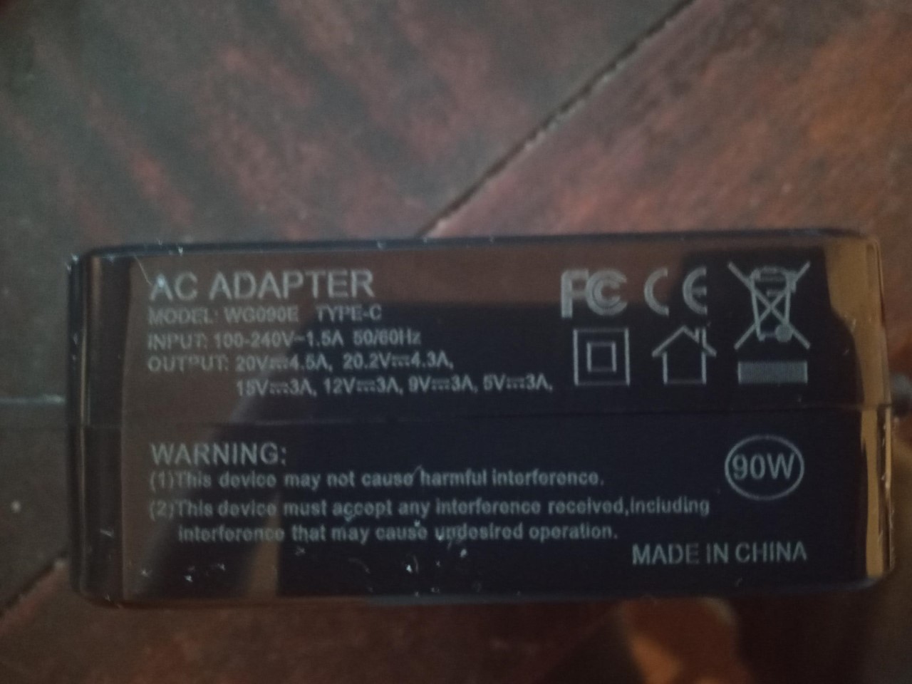
Have you read the messages before mine? 5V 1.5A is considered valid. Go ahead, plug in a WiFi card, a fan, an NVMe, some USB peripherals and see how that treats you. It needs handled unless they want users losing it 24/7 when their cheap PD supplies give less than 15 watts.
Nope but 5V 1.5A isn’t valid as with the efficiency of all the following bucks of approx 90% best scenario at each stage and additional peripherals it will need special configuration so don’t use, without special configuration .
The Rock5b can not use 5V 1.5A devices even if fed with 5.148V which is the minimum on that port normally, so its 5.148V 1.5A that is the special configuration and its only that if ‘dumb’ < 5.148V needs special configuration, not the other way around.
Anything dumb >= 5.148 <= 26v works without need of change, with 12v being a typical application.
So if you are going to use and be seriously borderline on power avail then a special configuration is needed not the other way round.
If you are going to bypass and provide 5v via GPIO then that is a different game.
Size wise PicoITX I guess its like Atx boards are but we don’t seem to have common mount holes that often ATX boards do whilst overall size is often ballpark. Its in the ballpark of PicoITX but as far as I know there are not any common cases because the I/O is not common and offered on multiple different planes.
That a PicoItx is all I/O and its a bit hard to make a common small case as you need an I/O plate punch out as like ATX mobo I/O is never the same.
The onboard switches for power & recovery could be swapped easily to just jumpers so that they can be wired switches or on relays as that would industrialise it with remote off possibility.
Would be great if gpio, DSI, CSI, HDMI-in & power button & recovery all had risers to sweep under the board via cables to a bracket and make a 2nd row of I/O all on that one plane.
The current CPU heatsink fan mounts are so off centre that I actually think my 40mm stick on is actually superior and maybe those could be lost or moved to some sort of other mount.
Prob a custom heatsink on the x3 mount holes and the heatsink mount near I/O could be used and that means the one near gpio could be reclaimed?
Anyone notice the M.2 rear mount pillar is maybe just 1mm off centre as on my board with a bit of a wiggle and how you pinch the NVME when mounted it didn’t matter but yeah its seems just off center.
Didn’t try the top PCIe2.0.
Yeah I would not swap the mounts to the 2007 PicoITX format as the mounts just steal I/O space and think that is one of the best features.
It would be great if they did a 1U panel as someone will do the math of how many you could fit side by side in 1U or more.
Thats why I like all the I/O on one plane as maybe I/O punch outs could be a thing but even Raspberry can not seem to keep to a singular compatible format.
Also the NVME mounts on board without some horrid riser in a bad attempt as a pseudo Pi format, is a huge plus.
Generally I like the format think its actually a big improvement on the Pi but doubt we will ever get a really universal format.
96boards was the same and also a sort of similar fail really.
Format wise apart from the cuteness of Zero type boards the Rock5B I would say is a definite fave.
That might be a Rock5A though as eagerly await whatever that maybe.
Maybe they might just do a single I/O punched out panel that is just a flat piece of thin steel with a big enough bezel (overlap) with mounting holes, that you can make a cut out and cover on any case, big enough?
More of a tidy than structural that just covers what makers may dremmel out?
I’m not disagreeing at all, I very much like the board’s layout. It just bothers me to call it Pico ITX. I can’t drill holes through a few sheets of acrylic in the same places and bolt them down, something necessary when claiming a form factor.
Exactly like the NanoPC-T4, which until now was my favorite form factor/optioned board.
Truly sticking to an existing standard beyond name alone helps.
Same not disagreeing, just doubting its possible as each SoC is so unique with I/O that sort of sets a format.
Maybe PicoITXish size is best we can do and have some things in the shop such as an I/O sheet maybe even a 1U multi Rock5b panel?
Generally I am loving what I see and maybe a few tweaks that are purely opinion.
Also maybe the onboard fan connector make it a more common JST 2.54mm as is it 2.0mm? My old eyes and vernier struggle.
It’s reporting the state of CC pins. AFAIK if there’s no USB PD involved CC pins can tell ‘5V @ 1.5A’ or ‘5V @ 3A’ so you need to blame your ‘DC-barrel plug to USB-C adapter’ for the state of CC pins?
Don’t you think this IC is there on all those RK3568/RK3588 thingies now since it’s part of Rockchip’s recent reference design?
And if situation with mainline kernel sucks a simple fix is needed, right?
I don’t think anything but V & Gnd is connected to anything on the DC-barrel female to USB-C as that is all they are.
There are some that go the other way and have a embeded PD chip to negotiate a voltage say 12v to a male barrel the other way but the female barrel to USB-C are just a pure hard wired adapter.
So would say that is the state reported when both CC disconnected maybe, would have to meter one out.
Since I learned yesterday that relevant ‘development talk’ around Rock 5B is happening in closed Discord channels without any public log I simply give up.
If people babbling about ‘open source’ able to choose freely between IRC and Discord choose the latter it’s time to say goodbye. As if the Snowden revelations never happened. People seem to like surveillance and being tracked everywhere. Just insane.
I agree about IRC & Discord as the public log gets lost, choice is choice and if that is what they use, that is what they use.
Its a shame you have to act like a baby in a pram on anything ‘you’ don’t like as often the info you provide is of value.
I’m not blaming anything. The board is unaware of what is actually coming in, so the user needs to watch out for that. You are correct, the CC pins give the cable current capability, 1.5 or 3A
I’ve tried that fix, it does not solve the issue, which it actually says in the linked patch note.
Here is the discussion of the issue that I recall after trying several versions of what you linked and settling on running the board on PoE: Making sure you're not a bot!
You running on pd-power? As try swapping to a Raspi5.1 or dumb psu and do an apt-get upgrade as yeah when on pd that looks like the boot loop I had wish I had copy+paste now with my memory.
I swapped out to a dumb 12v with usb-c adapter and things booted fine but also now the pd does boot fine and guess something was updated as haven’t changed anything myself as have just been running stress tests continiously
I tried several Apple laptop chargers and no luck (also using Apple cable): 29W, 87W and 96W. Those chargers work fine with Rock 3A and SSD. Rock 5b is without SSD.
I will try something else and see if I can get it to start.
Thanks for the suggestion.
Yeah I don’t have a emmc card either I presume I would of run apt-get upgrade whilst testing and an update fixed things as now this pd works fine, but I was the same with a boot loop.